Infiniti FX35, FX50 (S51). Manual — part 1828

MAIN POWER SUPPLY AND GROUND CIRCUIT
TM-119
< DTC/CIRCUIT DIAGNOSIS >
[7AT: RE7R01A (VQ35HR)]
C
E
F
G
H
I
J
K
L
M
A
B
TM
N
O
P
MAIN POWER SUPPLY AND GROUND CIRCUIT
Description
INFOID:0000000005250118
Supply power to TCM.
Diagnosis Procedure
INFOID:0000000005250119
1.
CHECK TCM POWER SOURCE (PART 1)
1.
Turn ignition switch OFF.
2.
Disconnect A/T assembly connector.
3.
Check voltage between A/T assembly vehicle side harness connector terminal and ground.
Is the inspection result normal?
YES
>> GO TO 2.
NO
>> GO TO 4.
2.
CHECK TCM POWER SOURCE (PART 2)
Check voltage between A/T assembly vehicle side harness connector terminals and ground.
Is the inspection result normal?
YES
>> GO TO 3.
NO
>> GO TO 5.
3.
CHECK TCM GROUND CIRCUIT
Check continuity between A/T assembly vehicle side harness connector terminals and ground.
Is the inspection result normal?
YES
>> Check intermittent incident. Refer to
GI-36, "Intermittent Incident"
.
NO
>> Repair or replace damaged parts.
4.
DETECT MALFUNCTIONING ITEM
Check the following.
• Harness for short or open between battery positive terminal and A/T assembly vehicle side harness connec-
PG-6, "Wiring Diagram - BATTERY POWER SUPPLY -"
• Battery
• 10A fuse (No.36, located in the fuse, fusible link and relay box). Refer to
PG-157, "Fuse and Fusible Link
.
Is the inspection result normal?
YES
>> Check intermittent incident. Refer to
GI-36, "Intermittent Incident"
.
NO
>> Repair or replace damaged parts.
A/T assembly vehicle side harness connector
Ground
Condition
Voltage (Approx.)
Connector
Terminal
F51
2
Always
Battery voltage
A/T assembly vehicle side harness connector
Ground
Condition
Voltage (Approx.)
Connector
Terminal
F51
1
Turn ignition switch ON
Battery voltage
Turn ignition switch OFF
0 V
6
Turn ignition switch ON
Battery voltage
Turn ignition switch OFF
0 V
A/T assembly vehicle side harness connector
Ground
Continuity
Connector
Terminal
F51
5
Existed
10

TM-120
< DTC/CIRCUIT DIAGNOSIS >
[7AT: RE7R01A (VQ35HR)]
MAIN POWER SUPPLY AND GROUND CIRCUIT
5.
CHECK HARNESS BETWEEN IPDM E/R AND A/T ASSEMBLY (PART 1)
1.
Turn ignition switch OFF.
2.
Disconnect IPDM E/R connector.
3.
Check continuity between IPDM E/R vehicle side harness connector terminal and A/T assembly vehicle
side harness connector terminals.
Is the inspection result normal?
YES
>> GO TO 6.
NO
>> Repair or replace damaged parts.
6.
CHECK HARNESS BETWEEN IPDM E/R AND A/T ASSEMBLY (PART 2)
Check continuity between A/T assembly vehicle side harness connector terminal and ground.
Is the inspection result normal?
YES
>> GO TO 7.
NO
>> Repair or replace damaged parts.
7.
DETECT MALFUNCTIONING ITEM
Check the following.
• Harness for short or open between ignition switch and IPDM E/R. Refer to
PG-81, "Wiring Diagram - IGNI-
• Ignition switch
• 10A fuse (No.43, located in the IPDM E/R). Refer to
PG-158, "Fuse, Connector and Terminal Arrangement"
.
• IPDM E/R
Is the inspection result normal?
YES
>> Check intermittent incident. Refer to
GI-36, "Intermittent Incident"
.
NO
>> Repair or replace damaged parts.
IPDM E/R vehicle side harness connector
A/T assembly vehicle side harness connector
Continuity
Connector
Terminal
Connector
Terminal
E7
58
F51
1
Existed
6
A/T assembly vehicle side harness connector
Ground
Continuity
Connector
Terminal
E51
1
Not existed
6

SHIFT POSITION INDICATOR CIRCUIT
TM-121
< DTC/CIRCUIT DIAGNOSIS >
[7AT: RE7R01A (VQ35HR)]
C
E
F
G
H
I
J
K
L
M
A
B
TM
N
O
P
SHIFT POSITION INDICATOR CIRCUIT
Description
INFOID:0000000005250120
TCM transmit the switch signals to unified meter and A/C amp. by CAN communication line. Then manual
mode switch position is indicated on the shift position indicator.
Component Function Check
INFOID:0000000005250121
1.
CHECK A/T INDICATOR
1.
Start the engine.
2.
Check the actual selector lever position (“P”, “R”, “N” and “D”) and the indication of the shift position indi-
cator mutually coincide.
3.
Drive vehicle in the manual mode, and then check that the actual gear position and the indication of the
position indicator mutually coincide when the selector lever is shifted to “UP (+ side)” or “DOWN (
−
side)”
side (1GR
⇔
7GR).
Is the inspection result normal?
YES
>> INSPECTION END
NO
>> Go to
Diagnosis Procedure
INFOID:0000000005250122
1.
CHECK INPUT SIGNALS
With CONSULT-III
1.
Start the engine.
2.
Select “SLCT LVR POSI” in “Data Monitor” in “TRANSMISSION”.
3.
Check the actual selector lever position (“P”, “R”, “N” and “D”) and the indication of the “SLCT LVR POSI”
mutually coincide. Refer to
.
4.
Drive vehicle in the manual mode, and then check that the actual gear position and the indication of the
“SLCT LVR POSI” mutually coincide when the selector lever is shifted to the “UP (+ side)” or “DOWN (
−
side)” side (1GR
⇔
7GR). Refer to
.
Is the inspection result normal?
YES
>> INSPECTION END
NO-1 [The actual gear position does not change, or shifting into the manual mode is not possible (no gear
shifting in the manual mode possible). Or the shift position indicator is not indicated.]>>•Check
manual
TM-113, "Component Inspection (Manual Mode Switch)"
• Check A/T main system (Fail-safe function actuated).
- Perform “Self Diagnostic Results” mode for “TRANSMISSION”. Refer to
.
NO-2 (The actual gear position changes, but the shift position indicator is not indicated.)>>•Perform
“Self
Diagnostic Results” mode for “TRANSMISSION”. Refer to
NO-3 (The actual gear position and the indication on the shift position indicator do not coincide.)>>•Perform
“Self Diagnostic Results” mode for “TRANSMISSION”. Refer to
.
NO-4 (Only a specific position or positions is/are not indicated on the shift position indicator.)>>•Check
the
unified meter and A/C amp. Refer to
.
TM-122
< DTC/CIRCUIT DIAGNOSIS >
[7AT: RE7R01A (VQ35HR)]
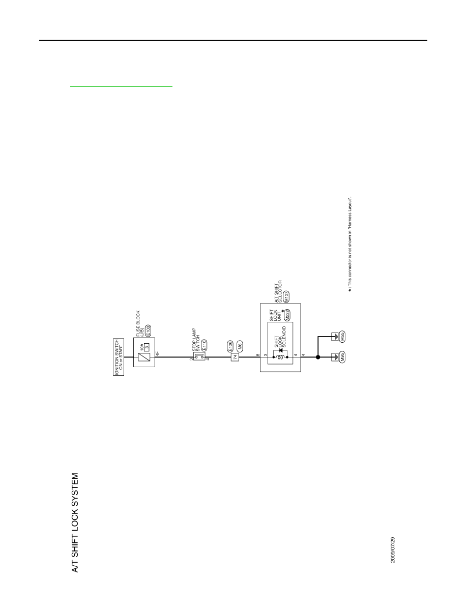
SHIFT LOCK SYSTEM
SHIFT LOCK SYSTEM
Description
INFOID:0000000005250123
Wiring Diagram - A/T SHIFT LOCK SYSTEM -
INFOID:0000000005250124
JCDWA0565GB
Нет комментариевНе стесняйтесь поделиться с нами вашим ценным мнением.
Текст