Infiniti FX35, FX50 (S51). Manual — part 936
EM-44
< REMOVAL AND INSTALLATION >
[VQ35HR]
FUEL INJECTOR AND FUEL TUBE
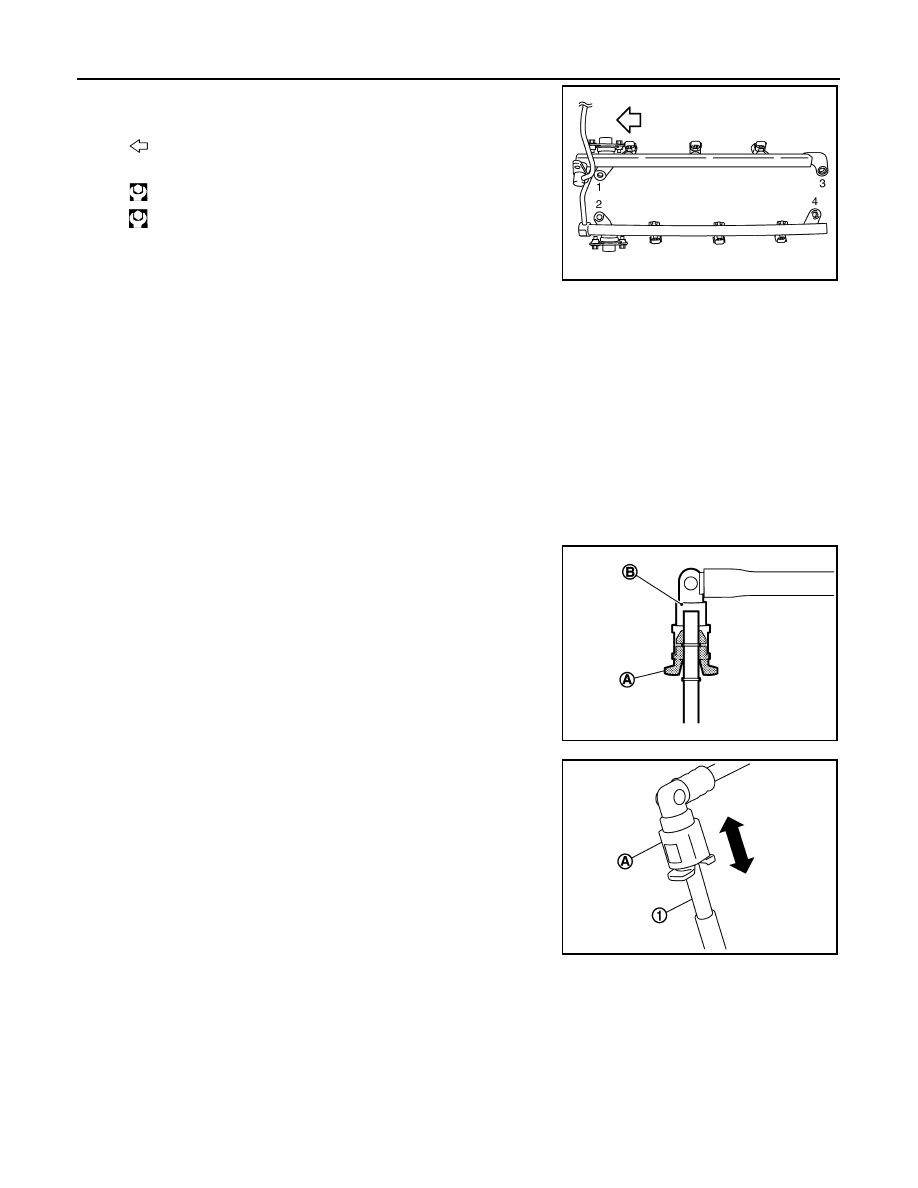
• Tighten mounting bolts in two steps in numerical order as
shown in the figure.
6.
Connect injector sub-harness.
7.
Install fuel sub tube mounting bolt.
8.
Connect fuel feed hose (with damper).
• Handling procedure of O-ring is the same as that of fuel damper and fuel sub-tube.
• Insert fuel damper straight into fuel sub-tube.
• Tighten mounting bolts evenly in turn.
• After tightening mounting bolts, check that there is no gap between flange and fuel sub-tube.
9.
Connect quick connector between fuel feed hose (with damper) and centralized under-floor piping con-
nection as per the following:
a.
Check no foreign substances are deposited in and around centralized under-floor piping and quick con-
nector, and no damage on them.
b.
Thinly apply new engine oil around centralized under-floor piping from tip end to spool end.
c.
Align center to insert quick connector straightly into centralized under-floor piping.
• Visually confirm that the two retainer tabs (A) are connected to
the quick connector (B).
CAUTION:
• Carefully align center to avoid inclined insertion to pre-
vent damage to O-ring inside quick connector.
• Insert until you hear a “click” sound and actually feel the
engagement.
• To avoid misidentification of engagement with a similar
sound, be sure to perform the next step.
d.
Pull quick connector by hand holding position (A). Check it is
completely engaged (connected) so that it does not come out
from centralized under-floor piping (1).
: Engine front
1st step
: 10.1 N·m (1.0 kg-m, 7 ft-lb)
2nd step
: 23.6 N·m (2.4 kg-m, 17 ft-lb)
JPBIA0034ZZ
JPBIA2378ZZ
PBIC3795E
FUEL INJECTOR AND FUEL TUBE
EM-45
< REMOVAL AND INSTALLATION >
[VQ35HR]
C
D
E
F
G
H
I
J
K
L
M
A
EM
N
P
O
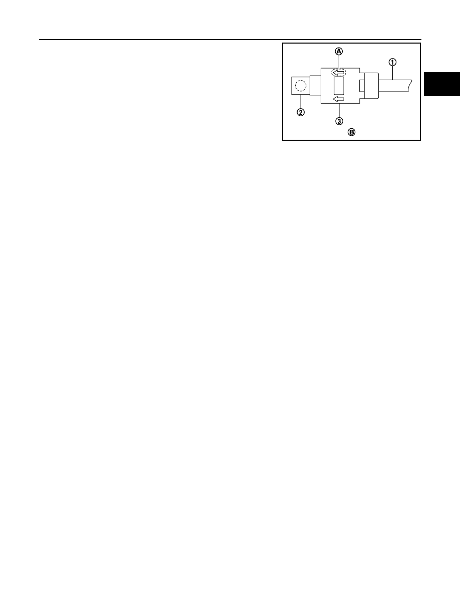
e.
Install quick connector cap (3) to quick connector connection.
• Install quick connector cap with arrow (A) on surface facing
the direction of quick connector (fuel feed hose side).
CAUTION:
If quick connector cap cannot be installed smoothly, quick
connector may have not be installed correctly. Check the
connection again.
10. Install in the reverse order of removal after this step.
Inspection
INFOID:0000000005245140
INSPECTION AFTER INSTALLATION
Check on Fuel Leakage
1.
Turn ignition switch “ON” (with the engine stopped). With fuel pressure applied to fuel piping, check there
are no fuel leakage at connection points.
NOTE:
Use mirrors for checking at points out of clear sight.
2.
Start the engine. With engine speed increased, check again that there are no fuel leakage at connection
points.
CAUTION:
Never touch the engine immediately after stopped, as the engine becomes extremely hot.
1
: Centralized under-floor piping
2
: Fuel feed hose
B
: Under view
JPBIA0039ZZ
EM-46
< REMOVAL AND INSTALLATION >
[VQ35HR]
OIL PAN (LOWER) AND OIL STRAINER
OIL PAN (LOWER) AND OIL STRAINER
Exploded View
INFOID:0000000005245141
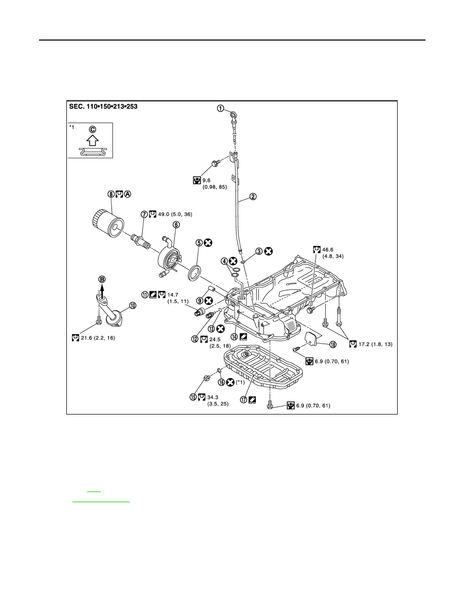
2WD models
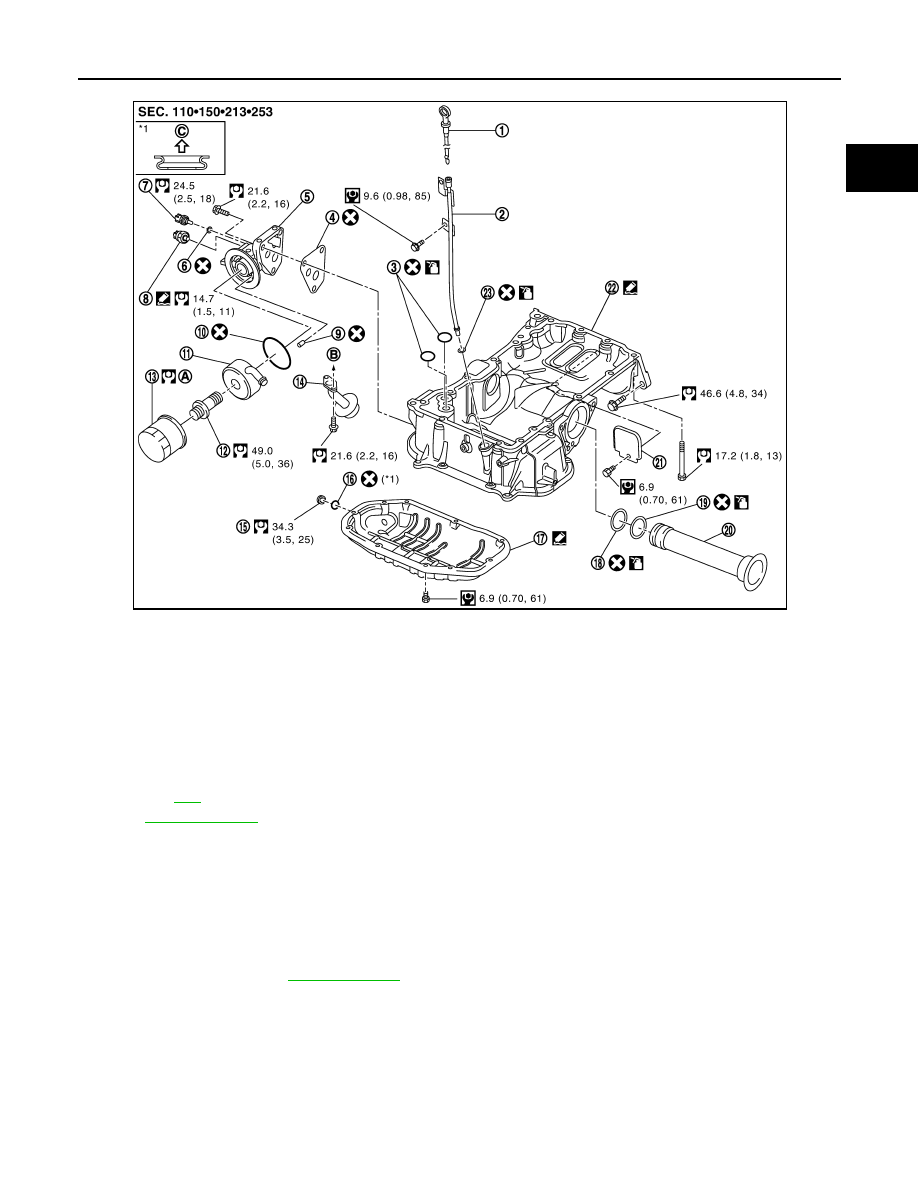
AWD
1.
Oil level gauge
2.
Oil level gauge guide
3.
O-ring
4.
O-ring
5.
O-ring
6.
Oil cooler
7.
Connector bolt
8.
Oil filter
9.
Relief valve
10. Oil strainer
11.
Oil pressure switch
12. Oil temperature sensor
13. Washer
14. Oil pan (upper)
15. Drain plug
16. Drain plug washer
17. Oil pan (lower)
18. Rear plate cover
A.
Refer to
B.
To oil pump
C.
Oil pan side
for symbols in the figure.
JPBIA1940GB
OIL PAN (LOWER) AND OIL STRAINER
EM-47
< REMOVAL AND INSTALLATION >
[VQ35HR]
C
D
E
F
G
H
I
J
K
L
M
A
EM
N
P
O
Removal and Installation
INFOID:0000000005245142
REMOVAL
WARNING:
To avoid the danger of being scalded, never drain engine oil when engine is hot.
1.
Remove engine undercover with power tool.
2.
Drain engine oil. Refer to
.
3.
Remove oil pan (lower) as per the following:
1.
Oil level gauge
2.
Oil level gauge guide
3.
O-ring
4.
Gasket
5.
Oil filter bracket
6.
Washer
7.
Oil temperature sensor
8.
Oil pressure sensor
9.
Relief valve
10. O-ring
11.
Oil cooler
12. Connector bolt
13. Oil filter
14. Oil strainer
15. Drain plug
16. Oil pan drain plug
17. Oil pan (lower)
18. O-ring (small)
19. O-ring (large)
20. Axle pipe
21. Rear plate cover
22. Oil pan (upper)
23. O-ring
A.
Refer to
B.
To oil pump
C.
Oil pan side
Refer to
for symbols in the figure.
JPBIA1847GB
Нет комментариевНе стесняйтесь поделиться с нами вашим ценным мнением.
Текст