Infiniti FX35, FX50 (S51). Manual — part 1386

MWI
FUEL LEVEL SENSOR SIGNAL CIRCUIT
MWI-63
< DTC/CIRCUIT DIAGNOSIS >
C
D
E
F
G
H
I
J
K
L
M
B
A
O
P
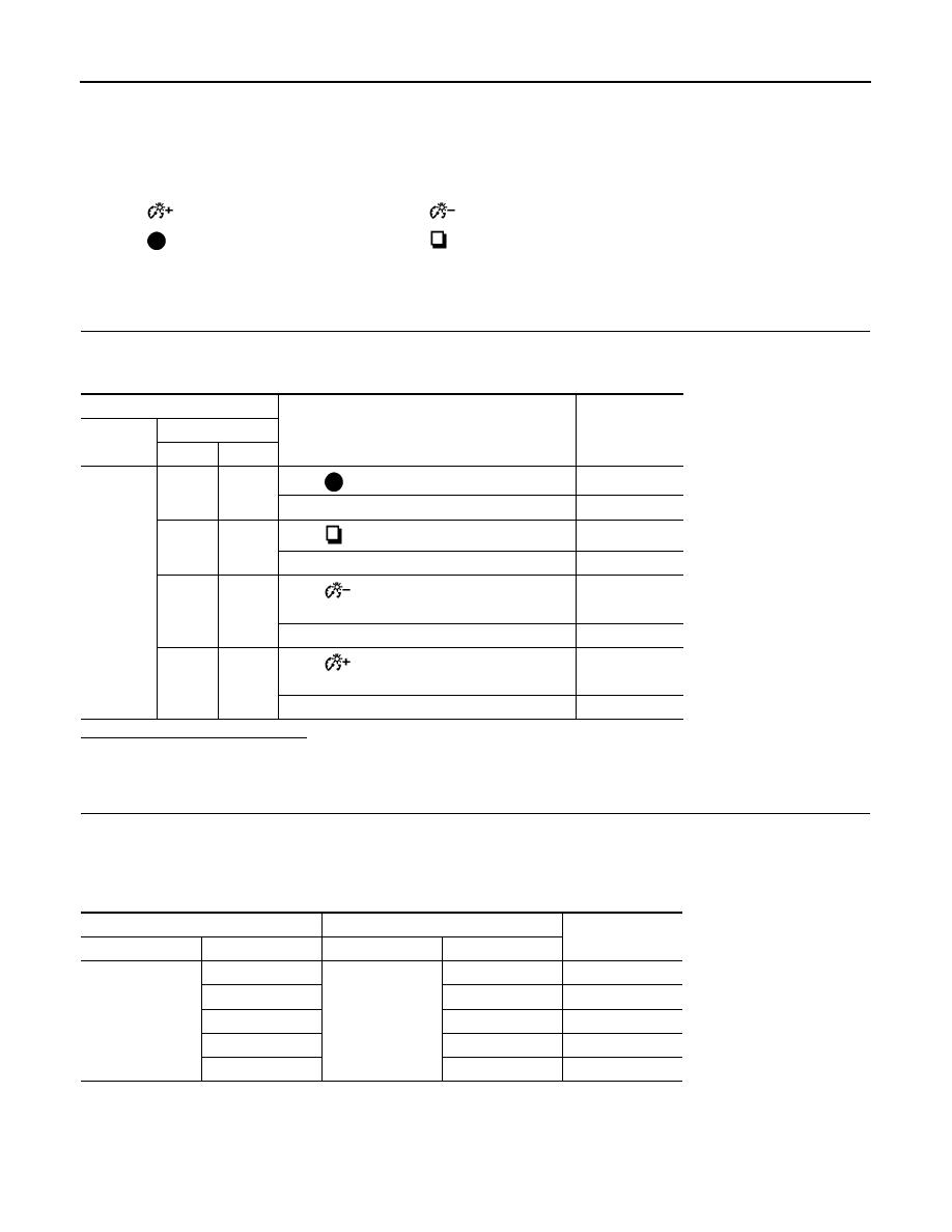
Check the resistance between fuel level sensor unit and fuel pump
(main).
Standard float position
*: When float rod is contact with stopper.
Is the inspection result normal?
YES
>> GO TO 3.
NO
>> Replace fuel level sensor unit and fuel pump (main).
3.
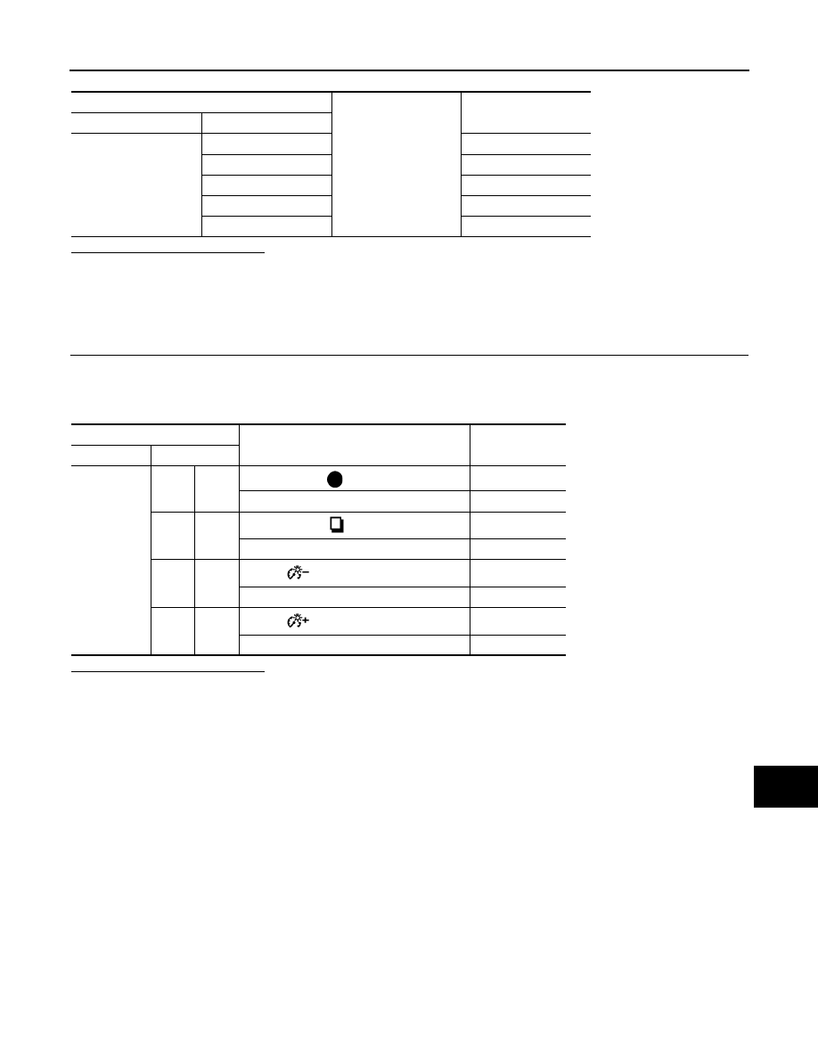
CHECK FUEL LEVEL SENSOR UNIT (SUB)
Inspect the resistance of fuel level sensor unit (sub).
Standard float position
*: When float rod is contact with stopper.
Is the inspection result normal?
YES
>> INSPECTION END
NO
>> Replace fuel level sensor unit (sub).
Fuel level sensor unit and fuel pump
(main)
Condition
Resistance
(Approx.)
Terminal
2
5
Full (A)
3
Ω
Empty (B)
80
Ω
JPNIA1110ZZ
Standard float position [mm (in)]
*
Full (A)
Approx. 223.8 (8.81)
Empty (B)
Approx. 29.4 (1.16)
Fuel level sensor unit (sub)
Condition
Resistance
(Approx.)
Terminal
1
2
Full (A)
3
Ω
Empty (B)
40
Ω
JPNIA1111ZZ
Standard float position [mm (in)]
*
Full (A)
Approx. 4.7 (0.19)
Empty (B)
Approx. 202.4 (7.97)
MWI-64
< DTC/CIRCUIT DIAGNOSIS >
METER CONTROL SWITCH SIGNAL CIRCUIT
METER CONTROL SWITCH SIGNAL CIRCUIT
Description
INFOID:0000000005524628
Transmits the following signals to the combination meter.
Diagnosis Procedure
INFOID:0000000005524629
1.
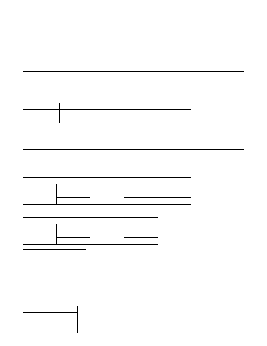
CHECK METER CONTROL SWITCH INPUT SIGNAL
1.
Turn the ignition switch ON.
2.
Check voltage between the following terminals of the combination meter.
Is the inspection result normal?
YES
>> INSPECTION END
NO
>> GO TO 2.
2.
CHECK METER CONTROL SWITCH SIGNAL CIRCUIT
1.
Turn the ignition switch OFF.
2.
Disconnect the combination meter and meter control switch connectors.
3.
Check continuity between combination meter harness connector and meter control switch harness con-
nector.
4.
Check continuity between combination meter harness connector and ground.
•
(Illumination control) switch signal (+)
•
(Illumination control) switch signal (–)
•
(select) switch signal
•
(enter) switch signal
Combination meter
Condition
Voltage
Connector
Terminal
(+)
(-)
M53
36
16
When
(select) switch is pressed
0 V
Other than the above
5 V
37
16
When
(enter) switch is pressed
0 V
Other than the above
5 V
39
16
When
(illumination control) switch is
pressed
0 V
Other than the above
5 V
40
16
When
(illumination control) switch is
pressed
0 V
Other than the above
5 V
Combination meter
Meter control switch
Continuity
Connector
Terminal
Connector
Terminal
M53
16
M54
2
Existed
36
6
Existed
37
7
Existed
39
3
Existed
40
1
Existed
MWI
METER CONTROL SWITCH SIGNAL CIRCUIT
MWI-65
< DTC/CIRCUIT DIAGNOSIS >
C
D
E
F
G
H
I
J
K
L
M
B
A
O
P
Is the inspection result normal?
YES
>> INSPECTION END
NO
>> Repair harness or connector.
Component Inspection
INFOID:0000000005524630
1.
CHECK METER CONTROL SWITCH UNIT
1.
Turn the ignition switch OFF.
2.
Disconnect the meter control switch connector.
3.
Check continuity between the following terminals of the meter control switch.
Is the inspection result normal?
YES
>> INSPECTION END
NO
>> Replace the meter control switch.
Combination meter
Ground
Continuity
Connector
Terminal
M53
16
Not existed
36
Not existed
37
Not existed
39
Not existed
40
Not existed
Combination meter
Operation and status
Continuity
Connector
Terminal
M54
6
2
Press
(select) switch
Existed
Other than the above
Not existed
7
2
Press
(enter) switch
Existed
Other than the above
Not existed
3
2
Press
(illumination control) switch
Existed
Other than the above
Not existed
1
2
Press
(illumination control) switch
Existed
Other than the above
Not existed
MWI-66
< DTC/CIRCUIT DIAGNOSIS >
TRIP A/B RESET SWITCH SIGNAL CIRCUIT
TRIP A/B RESET SWITCH SIGNAL CIRCUIT
Description
INFOID:0000000005524631
Transmits the trip A/B reset switch signals to the combination meter.
Diagnosis Procedure
INFOID:0000000005524632
1.
CHECK TRIP A/B RESET SWITCH INPUT SIGNAL
1.
Turn the ignition switch ON.
2.
Check voltage between the combination meter harness connector terminals.
Is the inspection result normal?
YES
>> INSPECTION END
NO
>> GO TO 2.
2.
CHECK TRIP A/B RESET SWITCH SIGNAL CIRCUIT
1.
Turn the ignition switch OFF.
2.
Disconnect the combination meter and meter control switch connectors.
3.
Check continuity between combination meter harness connector and trip A/B reset switch harness con-
nector.
4.
Check continuity between combination meter harness connector and ground.
Is the inspection result normal?
YES
>> INSPECTION END
NO
>> Repair harness or connector.
Component Inspection
INFOID:0000000005524633
1.
CHECK TRIP A/B RESET SWITCH UNIT
1.
Turn the ignition switch OFF.
2.
Disconnect the trip A/B reset switch connector.
3.
Check continuity between the trip A/B reset switch connector terminals.
Combination meter
Condition
Voltage
Connec-
tor
Terminal
(+)
(-)
M53
38
16
When trip A/B reset switch is pressed
0 V
Other than the above
5 V
Combination meter
Trip A/B reset switch
Continuity
Connector
Terminal
Connector
Terminal
M53
38
M56
1
Existed
16
2
Existed
Combination meter
Ground
Continuity
Connector
Terminal
M53
38
Not existed
16
Not existed
Combination meter
Operation and status
Continuity
Connector
Terminal
M56
1
2
Press trip A/B reset switch
Existed
Other than the above
Not existed
Нет комментариевНе стесняйтесь поделиться с нами вашим ценным мнением.
Текст