Infiniti FX35, FX50 (S51). Manual — part 1387
MWI
TRIP A/B RESET SWITCH SIGNAL CIRCUIT
MWI-67
< DTC/CIRCUIT DIAGNOSIS >
C
D
E
F
G
H
I
J
K
L
M
B
A
O
P
Is inspection result normal?
YES
>> INSPECTION END
NO
>> Replace the trip A/B reset switch.
MWI-68
< DTC/CIRCUIT DIAGNOSIS >
OIL PRESSURE SWITCH SIGNAL CIRCUIT
OIL PRESSURE SWITCH SIGNAL CIRCUIT
Description
INFOID:0000000005524634
Detects the engine oil pressure and transmits the oil pressure switch signal to IPDM E/R.
Component Function Check
INFOID:0000000005524635
1.
CHECK UNIFIED METER AND A/C AMP. INPUT SIGNAL
Select the “Data Monitor” for the “METER/M&A” and check the “OIL W/L” monitor value.
>> INSPECTION END
Diagnosis Procedure
INFOID:0000000005524636
1.
CHECK OIL PRESSURE SWITCH CIRCUIT
1.
Turn ignition switch OFF.
2.
Disconnect IPDM E/R connector and oil pressure switch connector.
3.
Check continuity between IPDM E/R harness connector and oil pressure switch harness connector.
4.
Check continuity between IPDM E/R harness connector and ground.
Is the inspection result normal?
YES
>> INSPECTION END
NO
>> Repair harness or connector.
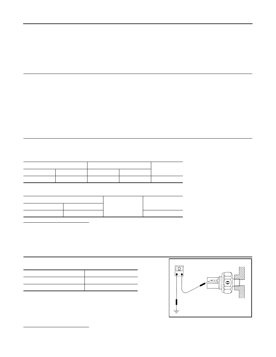
Component Inspection
INFOID:0000000005524637
1.
CHECK OIL PRESSURE SWITCH UNIT
Check continuity between oil pressure switch and ground.
Is the inspection result normal?
YES
>> INSPECTION END
NO
>> Replace the oil pressure switch.
“OIL W/L”
Ignition switch ON
: On
Engine running
: Off
IPDM E/R
Oil pressure switch
Continuity
Connector
Terminal
Connector
Terminal
E7
75
F37
1
Existed
IPDM E/R
Ground
Continuity
Connector
Terminal
E7
75
Not existed
Condition
Continuity
Engine stopped
Existed
Engine running
Not existed
ELF0044D
MWI
PARKING BRAKE SWITCH SIGNAL CIRCUIT
MWI-69
< DTC/CIRCUIT DIAGNOSIS >
C
D
E
F
G
H
I
J
K
L
M
B
A
O
P
PARKING BRAKE SWITCH SIGNAL CIRCUIT
Description
INFOID:0000000005524638
Transmits the parking brake switch signal to the combination meter.
Diagnosis Procedure
INFOID:0000000005524639
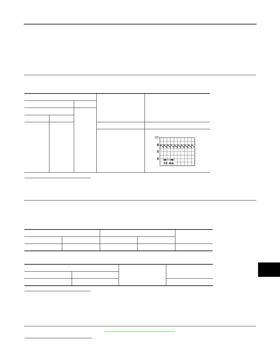
1.
CHECK COMBINATION METER INPUT SIGNAL
1.
Turn ignition switch ON.
2.
Check the voltage and waveform between combination meter harness connector and ground.
Is the inspection result normal?
YES
>> INSPECTION END
NO
>> GO TO 2.
2.
CHECK PARKING BRAKE SWITCH SIGNAL CIRCUIT
1.
Turn ignition switch OFF.
2.
Disconnect combination meter connector and parking brake switch connector.
3.
Check continuity between combination meter harness connector and parking brake switch harness con-
nector.
4.
Check continuity between combination meter harness connector and ground.
Is the inspection result normal?
YES
>> INSPECTION END
NO
>> Repair harness or connector.
Component Inspection
INFOID:0000000005524640
1.
CHECK PARKING BRAKE SWITCH
Check parking brake switch. Refer to
BRC-99, "Component Inspection"
Is the inspection result normal?
YES
>> INSPECTION END.
Terminals
Condition
Voltage and waveform
(+)
(-)
Combination meter
Ground
Connector
Terminal
M53
27
Parking brake applied
Approx. 0 V
Parking brake released
JSNIA0007GB
Combination meter
Parking brake switch
Continuity
Connector
Terminal
Connector
Terminal
M53
27
E107
1
Existed
Combination meter
Ground
Continuity
Connector
Terminal
M53
27
Not existed
MWI-70
< DTC/CIRCUIT DIAGNOSIS >
PARKING BRAKE SWITCH SIGNAL CIRCUIT
NO
>> Replace parking brake switch.
Нет комментариевНе стесняйтесь поделиться с нами вашим ценным мнением.
Текст