Infiniti FX35, FX50 (S51). Manual — part 345
CCS-200
< SYSTEM DESCRIPTION >
[DCA]
DIAGNOSIS SYSTEM (ICC SENSOR INTEGRATED UNIT)
DIAGNOSIS SYSTEM (ICC SENSOR INTEGRATED UNIT)
Diagnosis Description
INFOID:0000000005501782
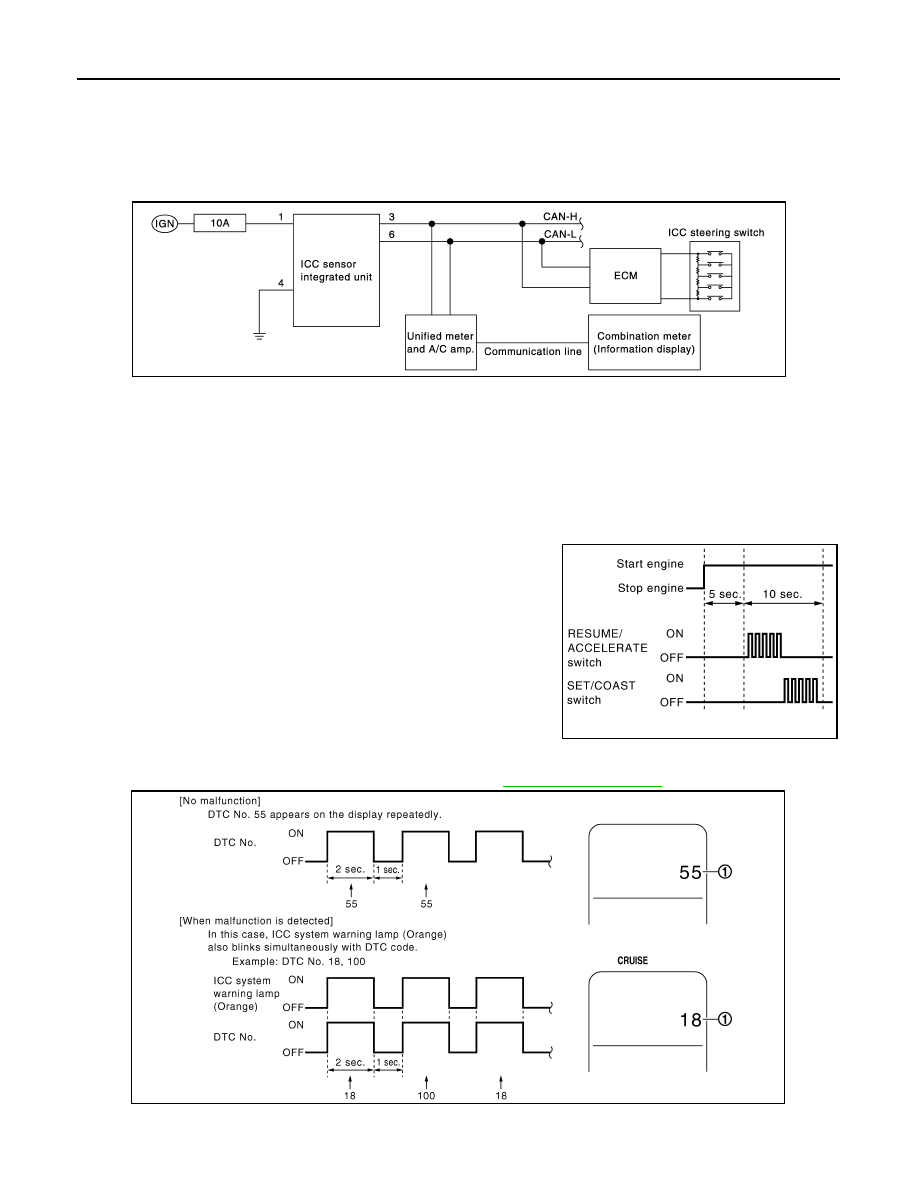
The DTC is displayed on the information display by operating the ICC steering switch.
ON BOARD SELF-DIAGNOSIS SYSTEM DIAGRAM
ON BOARD SELF-DIAGNOSIS OPERATION PROCEDURE
CAUTION:
Start condition of on board self-diagnosis
• ICC system OFF
• DCA system OFF
• Vehicle speed 0 km/h (0 MPH)
1.
Turn the ignition switch OFF.
2.
Start the engine.
3.
Wait for 5 seconds after starting the engine. Push up the
RESUME/ACCELERATE switch 5 times and push down the
SET/COAST switch 5 times within 10 seconds.
NOTE:
If the above operation cannot be performed within 10 seconds
after waiting for 5 seconds after starting the engine, repeat the
procedure from step 1.
4.
The DTC is displayed on the set vehicle speed indicator (1) on the ICC system display on the information
display when the on board self-diagnosis starts. Refer to
.
NOTE:
• It displays for up to 5 minutes and then stops.
JPOIA0189GB
PKIB8371E
JSOIA0008GB

CCS
DIAGNOSIS SYSTEM (ICC SENSOR INTEGRATED UNIT)
CCS-201
< SYSTEM DESCRIPTION >
[DCA]
C
D
E
F
G
H
I
J
K
L
M
B
N
P
A
• If multiple malfunctions exist, up to 3 DTCs can be stored in memory at the most, and the most recent
one is displayed first.
WHEN THE ON BOARD SELF-DIAGNOSIS DOES NOT START
If the on board self-diagnosis does not start, check the following items.
HOW TO ERASE ON BOARD SELF-DIAGNOSIS
1.
Turn the ignition switch OFF.
2.
Start the engine, and then start the on board self-diagnosis.
3.
Press the CANCEL switch 5 times, and then press the DIS-
TANCE switch 5 times under the condition that the on board
self-diagnosis starts.
NOTE:
• Complete the operation within 10 seconds after pressing the
CANCEL switch first.
• If the operation is not completed within 10 seconds, repeat the
procedure from step 1.
4.
DTC 55 is displayed after erasing.
NOTE:
DTCs for existing malfunction can not be erased.
5.
Turn ignition switch OFF, and finish the diagnosis.
CONSULT-III Function (ICC)
INFOID:0000000005501783
DESCRIPTION
CONSULT-III performs the following functions via CAN communication using ICC sensor integrated unit.
Assumed abnormal part
Inspection item
ICC system display
Combination meter malfunction
Check that the self-diagnosis function of the combina-
tion meter operates. Refer to
.
Unified meter and A/C amp. malfunction
Check power supply and ground circuit of unified meter
and A/C amp. Refer to
A/C AMP. : Diagnosis Procedure"
Communication error of the combination
meter and the unified meter and A/C amp.
Start the self-diagnosis of the unified meter and A/C
amp. and then check the self-diagnosis results. Refer to
ICC steering switch malfunction
Perform the inspection for DTC “C1A06”. Refer to
Harness malfunction between ICC steering switch and ECM
ECM malfunction
ICC sensor integrated unit malfunction
• Check power supply and ground circuit of ICC sensor
TEGRATED UNIT : Diagnosis Procedure"
• Perform SELF-DIAGNOSIS for “ICC” with CONSULT-
III, and then check the malfunctioning parts. Refer to
.
PKIB8373E
Diagnosis mode
Description
Work Support
• It can monitor the adjustment direction indication in order to perform the laser beam aiming operation
smoothly.
• Displays causes of automatic cancellation of the ICC system.
Self Diagnostic Result
Displays malfunctioning system memorized in ICC sensor integrated unit.
Data Monitor
Displays real-time input/output data of ICC sensor integrated unit.
Active Test
Enables operation check of electrical loads by transmitting driving signal to them.

CCS-202
< SYSTEM DESCRIPTION >
[DCA]
DIAGNOSIS SYSTEM (ICC SENSOR INTEGRATED UNIT)
WORK SUPPORT
Display Items For The Cause Of Automatic Cancellation
NOTE:
• Causes of the maximum five cancellations (system cancel) are displayed.
• The displayed cancellation causes display the number of the ignition switch ON/OFF up to 254. It is fixed to
254 if it is over 254. It returns to 0 when the same cancellation cause is detected again.
×
: Applicable
Ecu Identification
• Displays ICC sensor integrated unit part number.
• Displays brake booster control unit part number.
• Displays accelerator pedal assembly part number.
CAN Diag Support Monitor
The results of transmit/receive diagnosis of CAN communication can be read.
Diagnosis mode
Description
Work support items
Description
CAUSE OF AUTO-CANCEL
Displays causes of automatic cancellation of the ICC system.
LASER BEAM ADJUST
Outputs laser beam, calculates dislocation of the beam, and indicates adjustment direction.
Cause of cancellation
Vehicle-to-ve-
hicle distance
control mode
Conven-
tional
(fixed
speed)
cruise
control
mode
DCA
system
Description
OPERATING WIPER
×
The wiper operates at HI or LO (it includes when the wiper is op-
erated at LO or HI with the wiper switch INT position)
OPERATING ABS
×
×
ABS function was operated
OPERATING TCS
×
×
×
TCS function was operated
OPERATING VDC
×
×
×
VDC function was operated
ECM CIRCUIT
×
×
ECM did not permit ICC operation
OPE SW VOLT CIRC
×
×
×
The ICC steering switch input voltage is not within standard
range.
LASER SUNBEAM
×
×
Intense light such as sunlight entered ICC sensor integrated unit
light sensing part
LASER TEMP
×
×
Temperature around ICC sensor integrated unit became low
OP SW DOUBLE
TOUCH
×
×
ICC steering switches were pressed at the same time
WHL SPD ELEC NOISE
×
×
×
Wheel speed sensor signal caught electromagnetic noise
VDC/TCS OFF SW
×
×
VDC OFF switch was pressed
SNOW MODE SW
×
×
Snow mode switch was pressed
VHCL SPD UNMATCH
×
×
×
Wheel speed became different from A/T vehicle speed
TIRE SLIP
×
×
Wheel slipped
IGN LOW VOLT
×
×
×
Power supply voltage became low
WHEEL SPD UNMATCH
×
×
×
The wheel speeds of 4 wheels are out of the specified values
VHCL SPD DOWN
×
×
×
Vehicle speed lower than the speed as follows
• Vehicle-to-vehicle distance control mode is 24 km/h (15 MPH)
• Conventional (fixed speed) cruise control mode is 32 km/h (20
MPH)
CAN COMM ERROR
×
×
×
ICC sensor integrated unit received an abnormal signal with
CAN communication
ABS/TCS/VDC CIRC
×
×
×
An abnormal condition occurs in VDC/TCS/ABS system
BCU CIRCUIT
×
×
×
The brake booster control unit is malfunctioning

CCS
DIAGNOSIS SYSTEM (ICC SENSOR INTEGRATED UNIT)
CCS-203
< SYSTEM DESCRIPTION >
[DCA]
C
D
E
F
G
H
I
J
K
L
M
B
N
P
A
Laser Beam Adjust
CCS-13, "LASER BEAM AIMING ADJUSTMENT : Description"
.
SELF DIAGNOSTIC RESULT
DATA MONITOR
×
: Applicable
INCHING LOST
×
A vehicle ahead is not detected during the following driving when
the vehicle speed is approximately 24 km/h (15 MPH) or less
ASCD VHCL SPD DTAC
×
Vehicle speed is detached from set vehicle speed
ASCD DOUBLE COMD
×
Cancel switch and operation switch are detected simultaneously
PARKING BRAKE ON
×
×
The parking brake is operating
APA HI TEMP
×
The accelerator pedal actuator integrated motor temperature is
high
NO RECORD
×
×
×
−
Monitored item
[Unit]
MAIN
SIGNAL
Description
MAIN SW
[On/Off]
×
Indicates [On/Off] status as judged from ICC steering switch signal (ECM transmits
ICC steering switch signal through CAN communication).
SET/COAST SW
[On/Off]
×
Indicates [On/Off] status as judged from ICC steering switch signal (ECM transmits
ICC steering switch signal through CAN communication).
CANCEL SW
[On/Off]
×
Indicates [On/Off] status as judged from ICC steering switch signal (ECM transmits
ICC steering switch signal through CAN communication).
RESUME/ACC SW
[On/Off]
×
Indicates [On/Off] status as judged from ICC steering switch signal (ECM transmits
ICC steering switch signal through CAN communication).
DISTANCE SW
[On/Off]
Indicates [On/Off] status as judged from ICC steering switch signal (ECM transmits
ICC steering switch signal through CAN communication).
CRUISE OPE
[On/Off]
×
Indicates whether controlling or not (ON means “controlling”).
BRAKE SW
[On/Off]
×
Indicates [On/Off] status as judged from ICC brake switch signal (ECM transmits ICC
brake switch signal through CAN communication).
STOP LAMP SW
[On/Off]
×
Indicates [On/Off] status as judged from stop lamp switch signal (ECM transmits stop
lamp switch signal through CAN communication).
IDLE SW
[On/Off]
Indicates [On/Off] status of idle position read from ICC sensor integrated unit through
CAN communication (ECM transmits On/Off status through CAN communication).
SET DISTANCE
[Short/Mid/Long]
×
Indicates set distance memorized in ICC sensor integrated unit.
CRUISE LAMP
[On/Off]
×
Indicates [On/Off] status of MAIN switch indicator output.
OWN VHCL
[On/Off]
Indicates [On/Off] status of own vehicle indicator output.
VHCL AHEAD
[On/Off]
Indicates [On/Off] status of vehicle ahead detection indicator output.
ICC WARNING
[On/Off]
Indicates [On/Off] status of ICC system warning lamp output.
VHCL SPEED SE
[km/h] or [mph]
×
Indicates vehicle speed calculated from ICC sensor integrated unit through CAN
communication [ABS actuator and electric unit (control unit) transmits vehicle speed
signal (wheel speed) through CAN communication].
SET VHCL SPD
[km/h] or [mph]
×
Indicates set vehicle speed memorized in ICC sensor integrated unit.
BUZZER O/P
[On/Off]
Indicates [On/Off] status of ICC warning chime output.
Нет комментариевНе стесняйтесь поделиться с нами вашим ценным мнением.
Текст