Infiniti FX35, FX50 (S51). Manual — part 344
CCS-196
< SYSTEM DESCRIPTION >
[DCA]
DISTANCE CONTROL ASSIST SYSTEM
NOTE:
When the DCA system is automatically canceled, the cancellation condition can be displayed on “WORK SUPPORT” of CONSULT-III
(ICC).
ICC SENSOR INTEGRATED UNIT INPUT/OUTPUT SIGNAL ITEM
Input Signal Item
Condition
Description
Display on combination meter
Warning
display
When the DCA switch is turned ON
with settings of DCA system and LDP
system OFF
The DCA system is not activated. The DCA
system switch indicator blinks.
• When the VDC or ABS (including
the TCS) operates
• When the VDC is turned OFF
• When the snow mode switch is
turned ON
• When driving into a strong light
(i.e., sunlight)
The DCA system is automatically can-
celed. The chime will sound and the DCA
system switch indicator will blink.
NOTE:
The system operates if the DCA switch is
turned OFF
⇒
ON after the condition im-
proves.
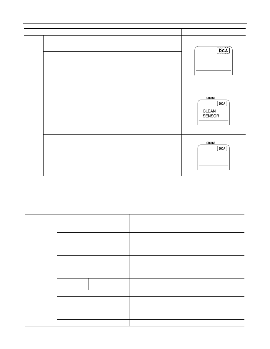
When the sensor window is dirty,
making it impossible to detect a vehi-
cle ahead
The DCA system is automatically can-
celed. The chime sounds and the ICC sys-
tem warning lamp will come on and the
“CLEAN SENSOR” indicator will appear.
NOTE:
Stop the vehicle in a safe location and turn
the ignition switch OFF. Clean the dirty
area with soft cloth. The system returns to
normal condition when turning the ignition
switch ON again.
When the DCA system is not operat-
ing properly
The chime sounds and the ICC system
warning lamp will come on.
NOTE:
Turn the ignition switch OFF, and then turn
the ignition switch ON again. If there is no
malfunction, the system returns to the nor-
mal condition.
JPOIA0165ZZ
JPOIA0166ZZ
JPOIA0167ZZ
Transmit unit
Signal name
Description
ECM
Accelerator pedal position signal
Receives the accelerator pedal position signal from ECM via CAN
communication.
ICC brake switch signal
Receives the ICC brake switch signal from ECM via CAN communi-
cation.
Stop lamp switch signal
Receives the stop lamp switch signal from ECM via CAN communi-
cation.
Closed throttle position signal
Receives the closed throttle position signal from ECM via CAN com-
munication.
Engine speed signal
Receives the engine speed signal from ECM via CAN communica-
tion.
ICC steering
switch signal
DCA switch signal
Receives the ICC steering switch signal (DCA switch signal) from
ECM via CAN communication.
TCM
Shift position signal
Receives the shift position signal from TCM via CAN communication.
Output shaft revolution signal
Receives the output shaft revolution signal from TCM via CAN com-
munication.
Current gear position signal
Receives the current gear position signal from TCM via CAN com-
munication.
Input speed signal
Receives the input speed signal from TCM via CAN communication.

CCS
DISTANCE CONTROL ASSIST SYSTEM
CCS-197
< SYSTEM DESCRIPTION >
[DCA]
C
D
E
F
G
H
I
J
K
L
M
B
N
P
A
Output Signal Item
Brake booster
control unit
Brake fluid pressure control signal
Receives the brake fluid pressure control signal from the brake
booster control unit via ITS communication.
Release switch signal
Receives the release switch signal from the brake booster control
unit via ITS communication.
ABS actuator
and electric unit
(control unit)
Vehicle speed signal
Receives the vehicle speed signal (wheel speed) from ABS actuator
and electric unit (control unit) via CAN communication.
AV control unit
System selection signal
Receives the system selection signal from the AV control unit via
CAN communication.
Steering angle
sensor
Steering angle sensor signal
Receives the steering angle sensor signal from the steering angle
sensor via CAN communication.
Accelerator ped-
al actuator
Accelerator pedal actuator status signal
Receives the accelerator pedal actuator status signal from the accel-
erator pedal actuator via ITS communication.
Transmit unit
Signal name
Description
Reception unit
Signal name
Description
Combination
meter (via uni-
fied meter and A/
C amp.)
Meter display
signal
Vehicle ahead detection
indicator signal
Transmits the meter display signal to the combination meter (via uni-
fied meter and A/C amp.) via CAN communication.
DCA system switch indi-
cator signal
ICC warning lamp signal
Transmits the ICC warning lamp signal to the combination meter
(through unified meter and A/C amp.) via CAN communication.
ICC warning
chime
Buzzer output signal
• Transmits the buzzer output signal to the brake booster control
unit via ITS communication.
• The brake booster control unit outputs the buzzer output signal
and operates the ICC warning chime.
ICC brake hold
relay
ICC brake hold relay drive signal
• Transmits the ICC brake hold relay drive signal to the brake boost-
er control unit via ITS communication.
• The brake booster control unit outputs the ICC brake hold relay
drive signal and operates the ICC brake hold relay.
Brake booster
control unit
Brake fluid pressure command signal
Transmits the brake fluid pressure command signal to the brake
booster control unit via ITS communication.
Accelerator ped-
al actuator
Accelerator pedal position signal
Transmits the accelerator pedal position signal received from ECM
via CAN communication to the accelerator pedal actuator via ITS
communication.
Accelerator pedal feedback force control
signal
Transmits the accelerator pedal feedback force control signal to the
accelerator pedal actuator via ITS communication.
CCS-198
< SYSTEM DESCRIPTION >
[DCA]
DISTANCE CONTROL ASSIST SYSTEM
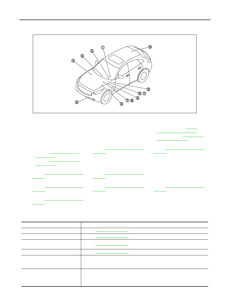
Component Parts Location
INFOID:0000000005501780
Component Description
INFOID:0000000005501781
1.
ICC steering switch
2.
Information display, ICC system
warning lamp
(On the combination meter)
3.
AV control unit
Refer to the following.
• With single monitor:
• With twin monitor:
4.
ECM
Refer to the following.
• VQ35HR:
• VK50VE:
5.
ICC sensor integrated unit
Refer to
6.
ICC brake hold relay
Refer to
.
7.
Booster solenoid/ Release switch
Refer to
.
8.
Brake pressure sensor
Refer to
9.
Accelerator pedal actuator (acceler-
ator pedal assembly)
10. Stop lamp switch
.
11.
ICC brake switch
Refer to
12. ICC warning chime
Refer to
.
13. Brake booster control unit
.
JSOIA0154GB
Component
Description
ICC sensor integrated unit
.
ECM
Refer to
.
ABS actuator and electric unit (control
unit)
.
TCM
.
Unified meter and A/C amp.
Receives the meter display signal and ICC warning lamp signal from ICC sensor integrat-
ed unit via CAN communication and transmits them to the combination meter via the com-
munication line.
Combination meter
• Perform the following operations using the signals received from the unified meter and
A/C amp. via the communication line.
- Displays the DCA system operation status using the meter display signal.
- Illuminates the ICC system warning lamp using the ICC warning lamp signal.

CCS
DISTANCE CONTROL ASSIST SYSTEM
CCS-199
< SYSTEM DESCRIPTION >
[DCA]
C
D
E
F
G
H
I
J
K
L
M
B
N
P
A
ICC brake switch
Stop lamp switch
ICC brake hold relay
Brake booster control unit
Brake booster
Brake pressure sensor
Booster solenoid/release switch
• Refer to
for booster solenoid.
• Refer to
ICC warning chime
Steering angle sensor
Accelerator pedal actuator
AV control unit
Transmits a system selection signal to the ICC sensor integrated unit via CAN communi-
cation.
Component
Description
Нет комментариевНе стесняйтесь поделиться с нами вашим ценным мнением.
Текст