Infiniti FX35, FX50 (S51). Manual — part 717
P1553 BATTERY CURRENT SENSOR
EC-409
< DTC/CIRCUIT DIAGNOSIS >
[VQ35HR]
C
D
E
F
G
H
I
J
K
L
M
A
EC
N
P
O
11.
CHECK BATTERY CURRENT SENSOR INPUT SIGNAL CIRCUIT FOR OPEN AND SHORT
1.
Check the continuity between battery current sensor harness connector and ECM harness connector.
2.
Also check harness for short to ground and short to power.
Is the inspection result normal?
YES
>> GO TO 13.
NO
>> GO TO 12.
12.
DETECT MALFUNCTIONING PART
Check the following.
• Harness connectors F1, E3
• Harness for open or short between battery current sensor and ECM
>> Repair open circuit, short to ground or short to power in harness or connectors.
13.
CHECK BATTERY CURRENT SENSOR
EC-409, "Component Inspection"
Is the inspection result normal?
YES
>> GO TO 14.
NO
>> Replace battery negative cable assembly.
14.
CHECK INTERMITTENT INCIDENT
GI-36, "Intermittent Incident"
.
>> INSPECTION END
Component Inspection
INFOID:0000000005237014
1.
CHECK BATTERY CURRENT SENSOR
1.
Turn ignition switch OFF.
2.
Reconnect harness connectors disconnected.
3.
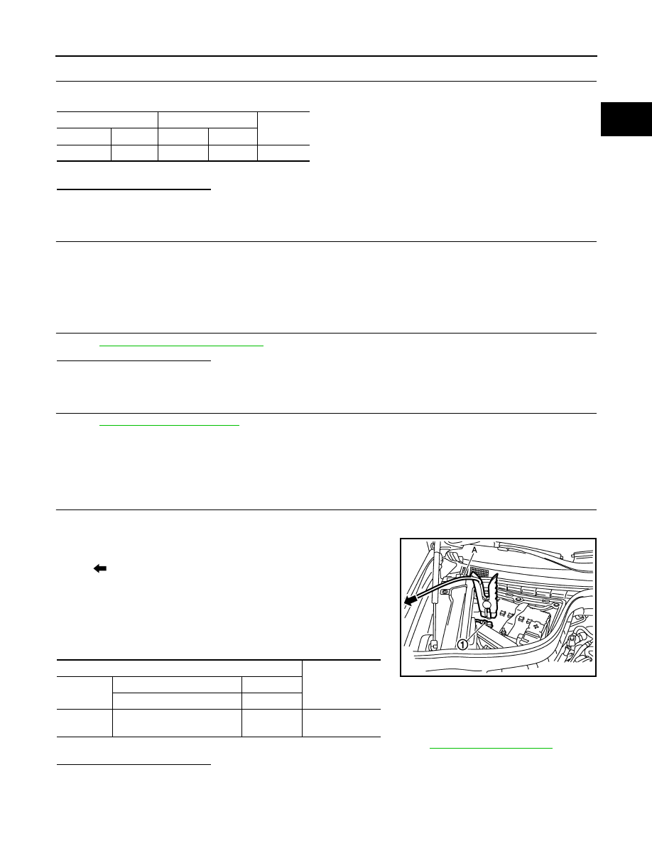
Disconnect battery negative cable (1).
4.
Install jumper cable (A) between battery negative terminal and
body ground.
5.
Turn ignition switch ON.
6.
Check the voltage between ECM harness connector terminals
as follows.
Before measuring the terminal voltage, confirm that the battery is fully charged. Refer to
.
Is the inspection result normal?
YES
>> INSPECTION END
NO
>> Replace battery negative cable assembly.
Battery current sensor
ECM
Continuity
Connector
Terminal
Connector
Terminal
E21
3
F102
91
Existed
: To body ground
ECM
Voltage (V)
Connector
+
–
Terminal
Terminal
F102
91
(Battery current sensor signal)
95
Approx. 2.5
JMBIA1512ZZ

EC-410
< DTC/CIRCUIT DIAGNOSIS >
[VQ35HR]
P1554 BATTERY CURRENT SENSOR
P1554 BATTERY CURRENT SENSOR
Description
INFOID:0000000005237015
The power generation voltage variable control enables fuel consumption to be decreased by reducing the
engine load which is caused by the power generation of the generator. The battery current sensor is installed
to the battery cable at the negative terminal. The sensor measures the charging/discharging current of the bat-
tery. Based on the sensor signal, ECM judges whether or not the power generation voltage variable control is
performed. When performing the power generation voltage variable control, ECM calculates the target power
generation voltage based on the sensor signal. And ECM sends the calculated value as the power generation
command value to IPDM E/R. For the details of the power generation voltage variable control, refer to
CAUTION:
Never connect the electrical component or the ground wire directly to the battery terminal. The con-
nection causes the malfunction of the power generation voltage variable control, and then battery dis-
charge may occur.
DTC Logic
INFOID:0000000005237016
DTC DETECTION LOGIC
DTC CONFIRMATION PROCEDURE
1.
PERFORM COMPONENT FUNCTION CHECK
Perform component function check. Refer to
EC-410, "Component Function Check"
NOTE:
Use component function check to check the overall function of the battery current sensor circuit. During this
check, a 1st trip DTC might not be confirmed.
Is the inspection result normal?
YES
>> INSPECTION END
NO
>> Go to
Component Function Check
INFOID:0000000005237017
1.
PRECONDITIONING
TESTING CONDITION:
• Before performing the following procedure, confirm that battery voltage is more than 12.8 V at idle.
DTC No.
Trouble diagnosis name
DTC detecting condition
Possible cause
P1554
Battery current sensor perfor-
mance
The output voltage of the battery current
sensor is lower than the specified value
while the battery voltage is high enough.
• Harness or connectors
(Battery current sensor circuit is open
or shorted.)
[Crankshaft position (CKP) sensor cir-
cuit is shorted.]
[Camshaft position (CMP) sensor
(bank 2) circuit is shorted.]
Exhaust valve timing (EVT) control po-
sition sensor (bank 2) circuit is short-
ed.]
[Accelerator pedal position (APP) sen-
sor 2 circuit is shorted.]
(EVAP control system pressure sensor
circuit is shorted.)
(Refrigerant pressure sensor circuit is
shorted.)
• Battery current sensor
• CKP sensor
• CMP sensor (bank 2)
• EVT control position sensor (bank 2)
• APP sensor
• EVAP control system pressure sensor
• Refrigerant pressure sensor

P1554 BATTERY CURRENT SENSOR
EC-411
< DTC/CIRCUIT DIAGNOSIS >
[VQ35HR]
C
D
E
F
G
H
I
J
K
L
M
A
EC
N
P
O
• Before performing the following procedure, confirm that all load switches and A/C switch are turned
OFF.
>> GO TO 2.
2.
PERFORM COMPONENT FUNCTION CHECK
With CONSULT-III
1.
Start engine and let it idle.
2.
Select “BAT CUR SEN” in “DATA MONITOR” mode with CONSULT-III.
3.
Check “BAT CUR SEN” indication for 10 seconds.
“BAT CUR SEN” should be above 2,300 mV at least once.
Without CONSULT-III
1.
Start engine and let it idle.
2.
Check the voltage between ECM harness connector terminals as follows.
Is the inspection result normal?
YES
>> INSPECTION END
NO
>> Go to
Diagnosis Procedure
INFOID:0000000005237018
1.
CHECK GROUND CONNECTION
1.
Turn ignition switch OFF.
2.
Check ground connection M95. Refer to Ground Inspection in
Is the inspection result normal?
YES
>> GO TO 2.
NO
>> Repair or replace ground connection.
2.
CHECK BATTERY CURRENT SENSOR POWER SUPPLY CIRCUIT-I
1.
Disconnect battery current sensor harness connector.
2.
Turn ignition switch ON.
3.
Check the voltage between battery current sensor harness connector and ground.
Is the inspection result normal?
YES
>> GO TO 9.
NO
>> GO TO 3.
3.
CHECK BATTERY CURRENT SENSOR POWER SUPPLY CIRCUIT-II
1.
Turn ignition switch OFF.
2.
Disconnect ECM harness connector.
3.
Check the continuity between battery current sensor harness connector and ECM harness connector.
Is the inspection result normal?
ECM
Voltage (V)
Connector
+
–
Terminal
Terminal
F102
91
(Battery current sensor signal)
95
Above 2.3 at least once
Battery current sensor
Ground
Voltage (V)
Connector
Terminal
E21
1
Ground
Approx. 5
Battery current sensor
ECM
Continuity
Connector
Terminal
Connector
Terminal
E21
1
F102
64
Existed

EC-412
< DTC/CIRCUIT DIAGNOSIS >
[VQ35HR]
P1554 BATTERY CURRENT SENSOR
YES
>> GO TO 5.
NO
>> GO TO 4.
4.
DETECT MALFUNCTIONING PART
Check the following.
• Harness connectors F1, E3
• Harness for open between battery current sensor and ECM
>> Repair open circuit.
5.
CHECK SENSOR POWER SUPPLY CIRCUIT
Check harness for short to power and short to ground, between the following terminals.
Is the inspection result normal?
YES
>> GO TO 6.
NO
>> Repair short to ground or short to power in harness or connectors.
6.
CHECK COMPONENTS
Check the following.
• CKP sensor (Refer to
EC-271, "Component Inspection"
• CMP sensor (bank 2) (Refer to
EC-277, "Component Inspection"
.)
• EVT control position sensor (bank 2) (Refer to
EC-369, "Component Inspection"
• EVAP control system pressure sensor (Refer to
EC-313, "Component Inspection"
.)
• Refrigerant pressure sensor (Refer to
Is the inspection result normal?
YES
>> GO TO 7.
NO
>> Replace malfunctioning component.
7.
CHECK APP SENSOR
EC-444, "Component Inspection"
Is the inspection result normal?
YES
>> GO TO 14.
NO
>> GO TO 8.
8.
REPLACE ACCELERATOR PEDAL ASSEMBLY
1.
Replace accelerator pedal assembly.
2.
Go to
EC-445, "Special Repair Requirement"
.
>> INSPECTION END
9.
CHECK BATTERY CURRENT SENSOR GROUND CIRCUIT FOR OPEN AND SHORT
1.
Turn ignition switch OFF.
ECM
Sensor
Connector
Terminal
Name
Connector
Terminal
F101
46
Crankshaft position (CKP) sensor
F2
1
F102
64
Camshaft position (CMP) sensor (bank 2)
F18
1
Exhaust valve timing (EVT) control posi-
tion sensor (bank 2)
F19
1
Battery current sensor
E21
1
M107
103
Accelerator pedal position (APP) sensor
E112
(Without ICC)
6
E116
(With ICC)
3
107
EVAP control system pressure sensor
B252
3
111
Refrigerant pressure sensor
E77
3
Нет комментариевНе стесняйтесь поделиться с нами вашим ценным мнением.
Текст