Infiniti FX35, FX50 (S51). Manual — part 225
BCS
COMBINATION SWITCH SYSTEM SYMPTOMS
BCS-81
< SYMPTOM DIAGNOSIS >
C
D
E
F
G
H
I
J
K
L
B
A
O
P
N
SYMPTOM DIAGNOSIS
COMBINATION SWITCH SYSTEM SYMPTOMS
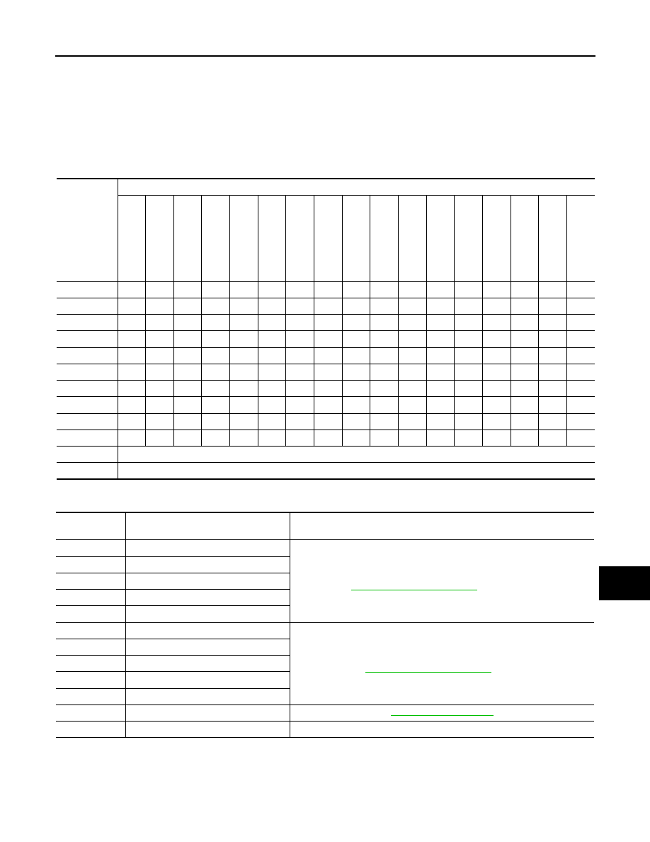
Symptom Table
INFOID:0000000005249346
1.
Perform “Data Monitor” of CONSULT-III to check for any malfunctioning item.
2.
Check the malfunction combinations.
Malfunction item:
×
3.
Identify the malfunctioning part from the agreed combination and repair or replace the part.
Malfunction
combination
Data monitor item
FR WI
PER HI
FR WIP
ER LOW
F
R
W
A
SH
ER
S
W
FR WI
PER INT
RR
WIPE
R
O
N
RR WIP
E
R INT
RR W
ASHER
SW
INT VOL
U
ME
TURN SIG
NAL R
TURN SIGNAL L
T
A
IL
LA
MP
SW
H
I BEAM SW
HEAD LAMP SW
1
HEAD LAMP SW
2
P
ASSI
N
G
SW
AU
T
O
LI
GH
T
S
W
FR F
O
G
SW
A
×
×
×
×
B
×
×
×
×
C
×
×
×
×
D
×
×
×
×
E
×
×
×
F
×
×
×
G
×
×
×
×
H
×
×
×
I
×
×
×
×
J
×
×
×
×
K
All Items
L
If only one item is detected or the item is not applicable to the combinations A to K
Malfunction
combination
Malfunctioning part
Repair or replace
A
Combination switch INPUT 1 circuit
Inspect the combination switch input circuit applicable to the malfunctioning
part. Refer to
.
B
Combination switch INPUT 2 circuit
C
Combination switch INPUT 3 circuit
D
Combination switch INPUT 4 circuit
E
Combination switch INPUT 5 circuit
F
Combination switch OUTPUT 1 circuit
Inspect the combination switch output circuit applicable to the malfunction-
ing part. Refer to
.
G
Combination switch OUTPUT 2 circuit
H
Combination switch OUTPUT 3 circuit
I
Combination switch OUTPUT 4 circuit
J
Combination switch OUTPUT 5 circuit
K
BCM
L
Combination switch
Replace the combination switch.
BCS-82
< PRECAUTION >
PRECAUTIONS
PRECAUTION
PRECAUTIONS
Precaution for Supplemental Restraint System (SRS) "AIR BAG" and "SEAT BELT
PRE-TENSIONER"
INFOID:0000000005249347
The Supplemental Restraint System such as “AIR BAG” and “SEAT BELT PRE-TENSIONER”, used along
with a front seat belt, helps to reduce the risk or severity of injury to the driver and front passenger for certain
types of collision. This system includes seat belt switch inputs and dual stage front air bag modules. The SRS
system uses the seat belt switches to determine the front air bag deployment, and may only deploy one front
air bag, depending on the severity of a collision and whether the front occupants are belted or unbelted.
Information necessary to service the system safely is included in the “SRS AIR BAG” and “SEAT BELT” of this
Service Manual.
WARNING:
• To avoid rendering the SRS inoperative, which could increase the risk of personal injury or death in
the event of a collision which would result in air bag inflation, all maintenance must be performed by
an authorized NISSAN/INFINITI dealer.
• Improper maintenance, including incorrect removal and installation of the SRS, can lead to personal
injury caused by unintentional activation of the system. For removal of Spiral Cable and Air Bag
Module, see the “SRS AIR BAG”.
• Do not use electrical test equipment on any circuit related to the SRS unless instructed to in this
Service Manual. SRS wiring harnesses can be identified by yellow and/or orange harnesses or har-
ness connectors.
PRECAUTIONS WHEN USING POWER TOOLS (AIR OR ELECTRIC) AND HAMMERS
WARNING:
• When working near the Air Bag Diagnosis Sensor Unit or other Air Bag System sensors with the
ignition ON or engine running, DO NOT use air or electric power tools or strike near the sensor(s)
with a hammer. Heavy vibration could activate the sensor(s) and deploy the air bag(s), possibly
causing serious injury.
• When using air or electric power tools or hammers, always switch the ignition OFF, disconnect the
battery, and wait at least 3 minutes before performing any service.
BCS
BCM (BODY CONTROL MODULE)
BCS-83
< REMOVAL AND INSTALLATION >
C
D
E
F
G
H
I
J
K
L
B
A
O
P
N
REMOVAL AND INSTALLATION
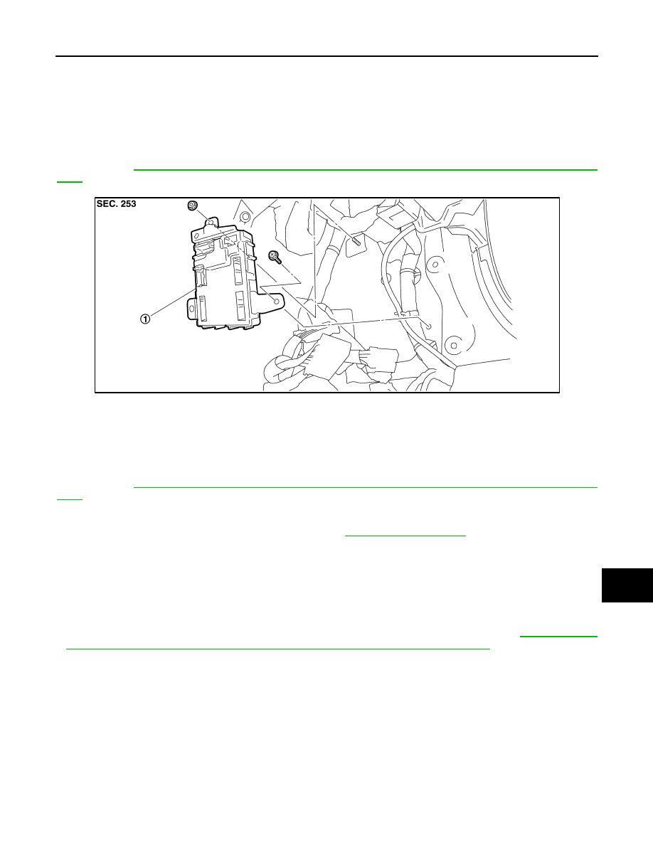
BCM (BODY CONTROL MODULE)
Exploded View
INFOID:0000000005249348
CAUTION:
Before replacing BCM, perform “READ CONFIGURATION” to save or print current vehicle specifica-
tion. Refer to
BCS-3, "ADDITIONAL SERVICE WHEN REPLACING CONTROL UNIT (BCM) : Descrip-
.
Removal and Installation
INFOID:0000000005249349
CAUTION:
Before replacing BCM, perform “READ CONFIGURATION” to save or print current vehicle specifica-
tion. Refer to
BCS-3, "ADDITIONAL SERVICE WHEN REPLACING CONTROL UNIT (BCM) : Descrip-
.
REMOVAL
1.
Remove dash side finisher (passenger side). Refer to
.
2.
Remove bolt and nut.
3.
Remove BCM and disconnect the connector.
INSTALLATION
Install in the reverse order of removal.
CAUTION:
• Be sure to perform “WRITE CONFIGURATION” when replacing BCM.
• Be sure to perform the system initialization (NATS) when replacing BCM. Refer to
TIONAL SERVICE WHEN REPLACING CONTROL UNIT (BCM) : Work Procedure"
.
1.
BCM
JPMIA1120ZZ
BCS-84
< REMOVAL AND INSTALLATION >
COMBINATION SWITCH
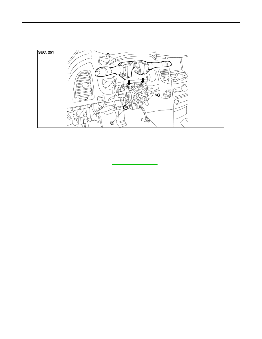
COMBINATION SWITCH
Exploded View
INFOID:0000000005249350
Removal and Installation
INFOID:0000000005249351
REMOVAL
1.
Remove steering column cover. Refer to
.
2.
Remove screws.
3.
Disconnect the connector.
4.
Pull up the combination switch to remove it.
INSTALLATION
Install in the reverse order of removal.
1.
Combination switch
2.
Combination switch connector
JPMIA1121ZZ
Нет комментариевНе стесняйтесь поделиться с нами вашим ценным мнением.
Текст