Infiniti FX35, FX50 (S51). Manual — part 226
BR-1
BRAKES
C
D
E
G
H
I
J
K
L
M
SECTION
BR
A
B
BR
N
O
P
CONTENTS
BRAKE SYSTEM
SYMPTOM DIAGNOSIS . . . . . . . ...
NOISE, VIBRATION AND HARSHNESS
(NVH) TROUBLESHOOTING . . . . . . . .
NVH Troubleshooting Chart . . . . . . . . . ..
PRECAUTION . . . . . . . . . . . ...
PRECAUTIONS . . . . . . . . . . . . ...
Precaution Necessary for Steering Wheel Rota-
tion after Battery Disconnect . . . . . . . . .....
Precaution for Procedure without Cowl Top Cover
. ..
Precaution for Brake System . . . . . . . . ....
PREPARATION . . . . . . . . . . .
PREPARATION . . . . . . . . . . . . ...
Commercial Service Tool . . . . . . . . . . ..
PERIODIC MAINTENANCE . . . . . . ..
BRAKE PEDAL . . . . . . . . . . . . ...
Inspection and Adjustment . . . . . . . . . ....
BRAKE FLUID . . . . . . . . . . . . .
Inspection . . . . . . . . . . . . . . . .
Draining . . . . . . . . . . . . . . . . ...
Refilling . . . . . . . . . . . . . . . . ...
Bleeding Brake System . . . . . . . . . . ...
BRAKE MASTER CYLINDER . . . . . . .
Inspection . . . . . . . . . . . . . . . .
BRAKE BOOSTER . . . . . . . . . . .
Inspection . . . . . . . . . . . . . . . .
FRONT DISC BRAKE . . . . . . . . . .
BRAKE PAD . . . . . . . . . . . . . . . ..
BRAKE PAD : Inspection and Adjustment . . . ..
DISC ROTOR . . . . . . . . . . . . . . . .
DISC ROTOR : Inspection and Adjustment . . . .
REAR DISC BRAKE . . . . . . . . . . .
BRAKE PAD . . . . . . . . . . . . . . . ..
BRAKE PAD : Inspection and Adjustment . . . ...
DISC ROTOR . . . . . . . . . . . . . . . .
DISC ROTOR : Inspection and Adjustment . . . .
REMOVAL AND INSTALLATION . . . ...
BRAKE PEDAL . . . . . . . . . . . . .
Exploded View . . . . . . . . . . . . . . .
Removal and Installation . . . . . . . . . . .
Inspection and Adjustment . . . . . . . . . ..
BRAKE PIPING . . . . . . . . . . . . .
FRONT . . . . . . . . . . . . . . . . . ...
FRONT : Exploded View . . . . . . . . . . .
FRONT : Hydraulic Piping . . . . . . . . . ...
FRONT : Removal and Installation . . . . . . ..
FRONT : Inspection . . . . . . . . . . . . .
REAR . . . . . . . . . . . . . . . . . . .
REAR : Exploded View . . . . . . . . . . .
REAR : Hydraulic Piping . . . . . . . . . . ..
REAR : Removal and Installation . . . . . . .
REAR : Inspection . . . . . . . . . . . . ...
BRAKE MASTER CYLINDER . . . . . . ..
Exploded View . . . . . . . . . . . . . . .
Removal and Installation . . . . . . . . . . .
Disassembly and Assembly . . . . . . . . . .
Inspection . . . . . . . . . . . . . . . .
BRAKE BOOSTER . . . . . . . . . . ...
Exploded View . . . . . . . . . . . . . . .
Removal and installation . . . . . . . . . . .
BR-2
VACUUM LINES . . . . . . . . . . . .
Exploded View . . . . . . . . . . . . . ....
Removal and Installation . . . . . . . . . ....
Inspection . . . . . . . . . . . . . . . ...
FRONT DISC BRAKE . . . . . . . . . .
BRAKE PAD (2 PISTON TYPE) . . . . . . . ...
BRAKE PAD (2 PISTON TYPE) : Exploded View ...
BRAKE PAD (2 PISTON TYPE) : Removal and In-
stallation . . . . . . . . . . . . . . . . .
BRAKE PAD (2 PISTON TYPE) : Inspection . . .
BRAKE PAD (4 PISTON TYPE) . . . . . . . ...
BRAKE PAD (4 PISTON TYPE) : Exploded View ...
BRAKE PAD (4 PISTON TYPE) : Removal and In-
stallation . . . . . . . . . . . . . . . . .
BRAKE PAD (4 PISTON TYPE) : Inspection . . .
BRAKE CALIPER ASSEMBLY (2 PISTON TYPE) ...
BRAKE CALIPER ASSEMBLY (2 PISTON TYPE)
: Exploded View . . . . . . . . . . . . . ..
BRAKE CALIPER ASSEMBLY (2 PISTON TYPE)
: Removal and Installation . . . . . . . . . ..
BRAKE CALIPER ASSEMBLY (2 PISTON TYPE)
: Disassembly and Assembly . . . . . . . . ..
BRAKE CALIPER ASSEMBLY (2 PISTON TYPE)
: Inspection . . . . . . . . . . . . . . . .
BRAKE CALIPER ASSEMBLY (4 PISTON TYPE) ...
BRAKE CALIPER ASSEMBLY (4 PISTON TYPE)
: Exploded View . . . . . . . . . . . . . ..
BRAKE CALIPER ASSEMBLY (4 PISTON TYPE)
: Removal and Installation . . . . . . . . . ..
BRAKE CALIPER ASSEMBLY (4 PISTON TYPE)
: Disassembly and Assembly . . . . . . . . ..
BRAKE CALIPER ASSEMBLY (4 PISTON TYPE)
: Inspection . . . . . . . . . . . . . . . .
REAR DISC BRAKE . . . . . . . . . . ..
BRAKE PAD (1 PISTON TYPE) . . . . . . . ...
BRAKE PAD (1 PISTON TYPE) : Exploded View ...
BRAKE PAD (1 PISTON TYPE) : Removal and In-
stallation . . . . . . . . . . . . . . . . ..
BRAKE PAD (1 PISTON TYPE) : Inspection . . ..
BRAKE PAD (2 PISTON TYPE) . . . . . . . ...
BRAKE PAD (2 PISTON TYPE) : Exploded View ...
BRAKE PAD (2 PISTON TYPE) : Removal and In-
stallation . . . . . . . . . . . . . . . . ..
BRAKE PAD (2 PISTON TYPE) : Inspection . . ..
BRAKE CALIPER ASSEMBLY (1 PISTON TYPE) ...
BRAKE CALIPER ASSEMBLY (1 PISTON TYPE)
: Exploded View . . . . . . . . . . . . . ..
BRAKE CALIPER ASSEMBLY (1 PISTON TYPE)
: Removal and Installation . . . . . . . . . ...
BRAKE CALIPER ASSEMBLY (1 PISTON TYPE)
: Disassembly and Assembly . . . . . . . . ..
BRAKE CALIPER ASSEMBLY (1 PISTON TYPE)
: Inspection . . . . . . . . . . . . . . . ..
BRAKE CALIPER ASSEMBLY (2 PISTON TYPE) ...
BRAKE CALIPER ASSEMBLY (2 PISTON TYPE)
: Exploded View . . . . . . . . . . . . . ..
BRAKE CALIPER ASSEMBLY (2 PISTON TYPE)
: Removal and Installation . . . . . . . . . ...
BRAKE CALIPER ASSEMBLY (2 PISTON TYPE)
: Disassembly and Assembly . . . . . . . . ..
BRAKE CALIPER ASSEMBLY (2 PISTON TYPE)
: Inspection . . . . . . . . . . . . . . . ..
SERVICE DATA AND SPECIFICATIONS
(SDS) . . . . . . . . . . . . . . ..
SERVICE DATA AND SPECIFICATIONS
(SDS) . . . . . . . . . . . . . . . . .
General Specifications . . . . . . . . . . .
Brake Pedal . . . . . . . . . . . . . . .
Brake Booster . . . . . . . . . . . . . . .
Front Disc Brake . . . . . . . . . . . . . .
NOISE, VIBRATION AND HARSHNESS (NVH) TROUBLESHOOTING
BR-3
< SYMPTOM DIAGNOSIS >
C
D
E
G
H
I
J
K
L
M
A
B
BR
N
O
P
SYMPTOM DIAGNOSIS
NOISE, VIBRATION AND HARSHNESS (NVH) TROUBLESHOOTING
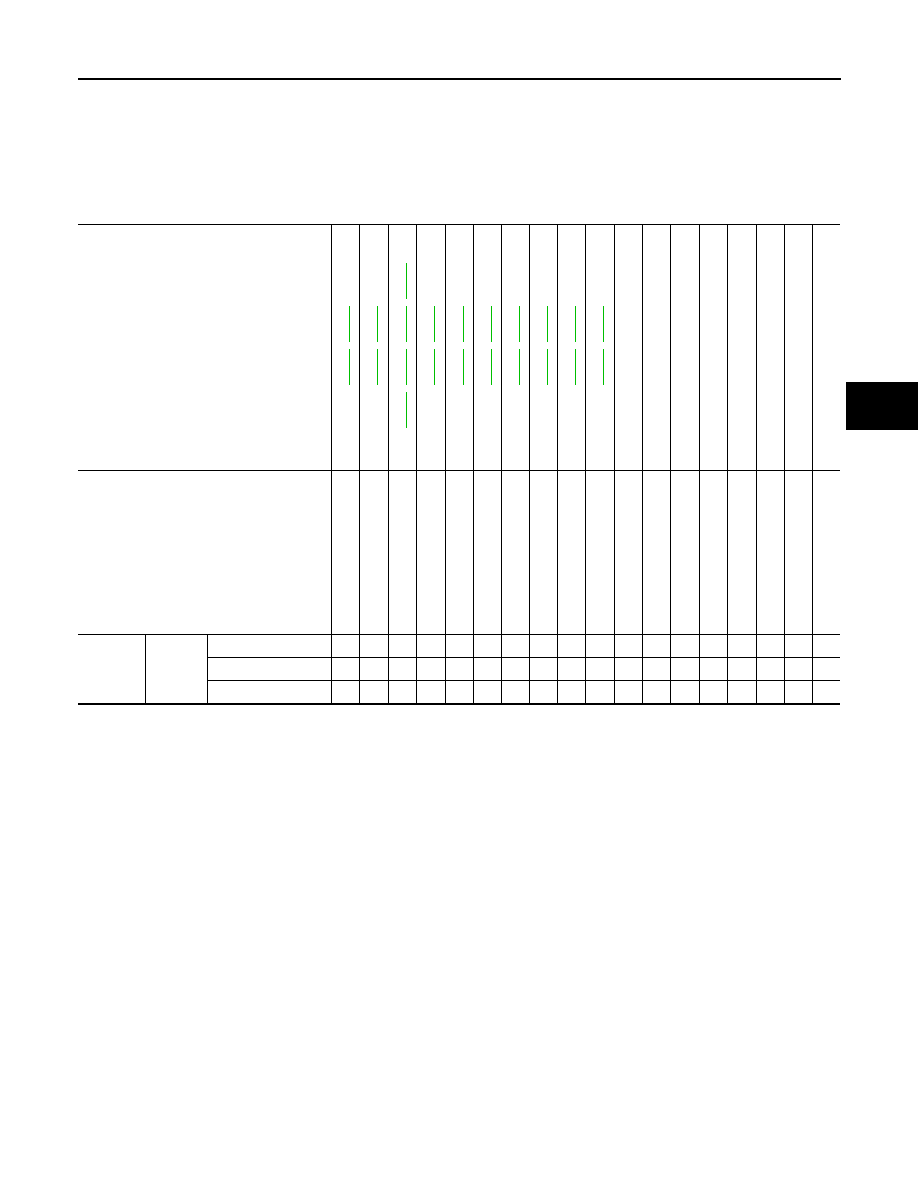
NVH Troubleshooting Chart
INFOID:0000000005234157
Use the chart below to find the cause of the symptom. If necessary, repair or replace these parts.
×
: Applicable
Reference page
,
,
,
,
,
,
,
,
,
,
,
,
NVH in PB
section
NVH in DLN
section
NHV in DLN
section
NVH in F
AX, RAX
and FSU, RSU section
NVH in WT
se
ct
io
n
NVH in WT
se
ct
io
n
NVH in F
AX and/or
R
A
X section
NVH in ST
section
Possible cause and
SUSPECTED PARTS
Pad
s - da
ma
ge
d
Pad
s - un
ev
en
wea
r
Shi
ms
da
ma
ge
d
Ro
to
r im
ba
la
nc
e
Ro
to
r da
ma
ge
Rot
o
r runout
Ro
to
r de
fo
rm
a
tio
n
Ro
to
r de
fl
e
c
ti
o
n
Rot
o
r rust
Ro
to
r th
ic
kn
es
s va
ri
ati
o
n
Drum
o
u
t of
rou
n
d
PROPELLER SHAFT
DIFF
ERENTIAL
AXLE AND S
U
SPENSION
TI
RE
ROAD WHEE
L
DRIVE SHAFT
STE
E
RING
Symptom
BRAKE
Noise
×
×
×
×
×
×
×
×
×
×
Shake
×
×
×
×
×
×
×
Shimmy, Judder
×
×
×
×
×
×
×
×
×
×
×
BR-4
< PRECAUTION >
PRECAUTIONS
PRECAUTION
PRECAUTIONS
Precaution for Supplemental Restraint System (SRS) "AIR BAG" and "SEAT BELT
PRE-TENSIONER"
INFOID:0000000005531135
The Supplemental Restraint System such as “AIR BAG” and “SEAT BELT PRE-TENSIONER”, used along
with a front seat belt, helps to reduce the risk or severity of injury to the driver and front passenger for certain
types of collision. This system includes seat belt switch inputs and dual stage front air bag modules. The SRS
system uses the seat belt switches to determine the front air bag deployment, and may only deploy one front
air bag, depending on the severity of a collision and whether the front occupants are belted or unbelted.
Information necessary to service the system safely is included in the “SRS AIR BAG” and “SEAT BELT” of this
Service Manual.
WARNING:
• To avoid rendering the SRS inoperative, which could increase the risk of personal injury or death in
the event of a collision which would result in air bag inflation, all maintenance must be performed by
an authorized NISSAN/INFINITI dealer.
• Improper maintenance, including incorrect removal and installation of the SRS, can lead to personal
injury caused by unintentional activation of the system. For removal of Spiral Cable and Air Bag
Module, see the “SRS AIR BAG”.
• Do not use electrical test equipment on any circuit related to the SRS unless instructed to in this
Service Manual. SRS wiring harnesses can be identified by yellow and/or orange harnesses or har-
ness connectors.
PRECAUTIONS WHEN USING POWER TOOLS (AIR OR ELECTRIC) AND HAMMERS
WARNING:
• When working near the Air Bag Diagnosis Sensor Unit or other Air Bag System sensors with the
ignition ON or engine running, DO NOT use air or electric power tools or strike near the sensor(s)
with a hammer. Heavy vibration could activate the sensor(s) and deploy the air bag(s), possibly
causing serious injury.
• When using air or electric power tools or hammers, always switch the ignition OFF, disconnect the
battery, and wait at least 3 minutes before performing any service.
Precaution Necessary for Steering Wheel Rotation after Battery Disconnect
INFOID:0000000005531136
NOTE:
• Before removing and installing any control units, first turn the push-button ignition switch to the LOCK posi-
tion, then disconnect both battery cables.
• After finishing work, confirm that all control unit connectors are connected properly, then re-connect both
battery cables.
• Always use CONSULT-III to perform self-diagnosis as a part of each function inspection after finishing work.
If a DTC is detected, perform trouble diagnosis according to self-diagnosis results.
For vehicle with steering lock unit, if the battery is disconnected or discharged, the steering wheel will lock and
cannot be turned.
If turning the steering wheel is required with the battery disconnected or discharged, follow the operation pro-
cedure below before starting the repair operation.
OPERATION PROCEDURE
1.
Connect both battery cables.
NOTE:
Supply power using jumper cables if battery is discharged.
2.
Turn the push-button ignition switch to ACC position.
(At this time, the steering lock will be released.)
3.
Disconnect both battery cables. The steering lock will remain released with both battery cables discon-
nected and the steering wheel can be turned.
4.
Perform the necessary repair operation.
Нет комментариевНе стесняйтесь поделиться с нами вашим ценным мнением.
Текст