Infiniti FX35, FX50 (S51). Manual — part 258
C1115 WHEEL SENSOR
BRC-63
< DTC/CIRCUIT DIAGNOSIS >
[VDC/TCS/ABS]
C
D
E
G
H
I
J
K
L
M
A
B
BRC
N
O
P
Measurement terminal for power supply circuit
Measurement terminal for signal circuit
2.
Check the continuity between ABS actuator and electric unit (control unit) harness connector.
Is the inspection result normal?
YES
>> GO TO 5.
NO
>> Repair or replace error-detected parts.
5.
REPLACE WHEEL SENSOR
1.
Replace wheel sensor.
2.
Erase self-diagnosis results for “ABS” with CONSULT-III.
3.
Turn the ignition switch OFF.
4.
Turn the ignition switch ON.
CAUTION:
Never start the engine.
5.
Perform self-diagnosis for “ABS” with CONSULT-III.
Is DTC “C1115” detected?
YES
>> Replace ABS actuator and electric unit (control unit).
NO
>> INSPECTION END
Special Repair Requirement
INFOID:0000000005528310
1.
ADJUSTMENT OF STEERING ANGLE SENSOR NEUTRAL POSITION
Always perform the neutral position adjustment for the steering angle sensor, when replacing the ABS actua-
tor and electric unit (control unit). Refer to
BRC-9, "ADJUSTMENT OF STEERING ANGLE SENSOR NEU-
>> END
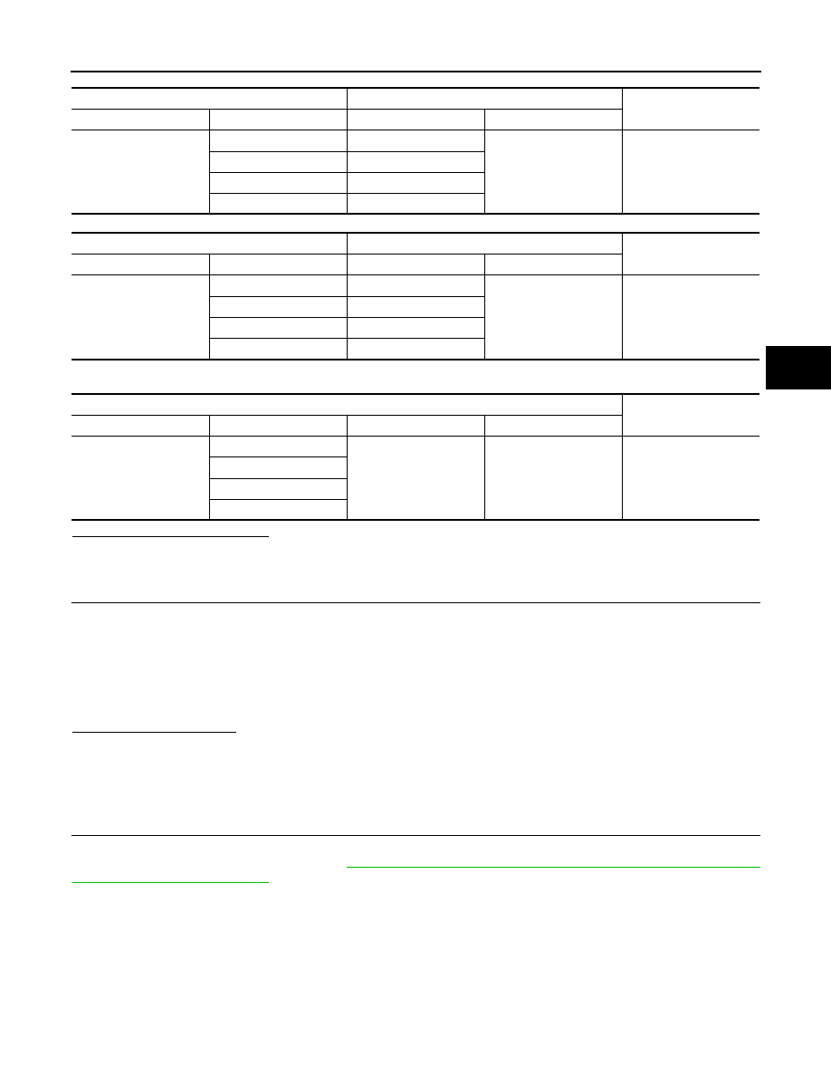
ABS actuator and electric unit (control unit)
Wheel sensor
Continuity
Connector
Terminal
Connector
Terminal
E41
9
E27 (Front RH)
1
Existed
26
E60 (Front LH)
7
B33 (Rear RH)
6
B34 (Rear LH)
ABS actuator and electric unit (control unit)
Wheel sensor
Continuity
Connector
Terminal
Connector
Terminal
E41
10
E27 (Front RH)
2
Existed
5
E60 (Front LH)
29
B33 (Rear RH)
27
B34 (Rear LH)
ABS actuator and electric unit (control unit)
Continuity
Connector
Terminal
Connector
Terminal
E41
9, 10
E41
1, 4
Not existed
26, 5
7, 29
6, 27

BRC-64
< DTC/CIRCUIT DIAGNOSIS >
[VDC/TCS/ABS]
C1116 STOP LAMP SWITCH
C1116 STOP LAMP SWITCH
Description
INFOID:0000000005234530
The stop lamp switch transmits the stop lamp switch signal (ON/OFF) to the ABS actuator and electric unit
(control unit).
DTC Logic
INFOID:0000000005234531
DTC DETECTION LOGIC
DTC CONFIRMATION PROCEDURE
1.
DTC REPRODUCTION PROCEDURE
1.
Turn the ignition switch ON.
2.
Perform self-diagnosis for “ABS” with CONSULT-III.
Is DTC “C1116” detected?
YES
>> Proceed to diagnosis procedure. Refer to
.
NO
>> INSPECTION END
Diagnosis Procedure
INFOID:0000000005234532
1.
CHECK CONNECTOR
1.
Turn the ignition switch OFF.
2.
Disconnect ABS actuator and electric unit (control unit) harness connector.
3.
Disconnect stop lamp switch harness connector.
4.
Check terminal for deformation, disconnection, looseness, etc.
5.
Reconnect ABS actuator and electric unit (control unit) and stop lamp switch harness connectors
securely.
6.
Start the engine.
7.
Repeat pumping brake pedal carefully several times, and perform self-diagnosis for “ABS” with CON-
SULT-III.
Is the inspection result normal?
YES
>> GO TO 2.
NO
>> Poor connection of harness connector terminal. Repair or replace error-detected parts.
2.
CHECK STOP LAMP SWITCH CLEARANCE
Check stop lamp switch clearance. Refer to
BR-7, "Inspection and Adjustment"
.
Is the inspection result normal?
YES
>> GO TO 3.
NO
>> Adjust stop lamp switch clearance. Refer to
BR-7, "Inspection and Adjustment"
.
3.
CHECK STOP LAMP SWITCH
Check stop lamp switch. Refer to
BRC-65, "Component Inspection"
Is the inspection result normal?
YES
>> GO TO 4.
NO
>> Replace stop lamp switch. Refer to
.
4.
CHECK STOP LAMP SWITCH CIRCUIT
Check the voltage between ABS actuator and electric unit (control unit) harness connector and ground.
DTC
Display item
Malfunction detected condition
Possible cause
C1116
STOP LAMP SW
When a stop lamp switch signal is not input where the
brake pedal is depressed.
• Harness or connector
• Stop lamp switch
• ABS actuator and electric unit
(control unit)

C1116 STOP LAMP SWITCH
BRC-65
< DTC/CIRCUIT DIAGNOSIS >
[VDC/TCS/ABS]
C
D
E
G
H
I
J
K
L
M
A
B
BRC
N
O
P
Is the inspection result normal?
YES
>> Replace ABS actuator and electric unit (control unit).
NO
>> Repair or replace error-detected parts.
Component Inspection
INFOID:0000000005234533
1.
CHECK STOP LAMP SWITCH
1.
Turn the ignition switch OFF.
2.
Disconnect stop lamp switch harness connector.
3.
Check the continuity between stop lamp switch harness connector terminals.
Is the inspection result normal?
YES
>> INSPECTION END
NO
>> Replace stop lamp switch. Refer to
.
Special Repair Requirement
INFOID:0000000005528311
1.
ADJUSTMENT OF STEERING ANGLE SENSOR NEUTRAL POSITION
Always perform the neutral position adjustment for the steering angle sensor, when replacing the ABS actua-
tor and electric unit (control unit). Refer to
BRC-9, "ADJUSTMENT OF STEERING ANGLE SENSOR NEU-
>> END
ABS actuator and electric unit (control unit)
Condition
Voltage
Connector
Terminal
E41
30
Brake pedal is depressed
Battery voltage
Brake pedal is released
Approx. 0 V
Stop lamp switch
Condition
Continuity
Terminal
1 – 2
Release stop lamp switch
(When brake pedal is depressed.)
Existed
Push stop lamp switch
(When brake pedal is released.)
Not existed

BRC-66
< DTC/CIRCUIT DIAGNOSIS >
[VDC/TCS/ABS]
C1120, C1122, C1124, C1126 IN ABS SOL
C1120, C1122, C1124, C1126 IN ABS SOL
Description
INFOID:0000000005234535
The solenoid valve increases, holds or decreases the fluid pressure of each brake caliper according to the sig-
nals transmitted by the ABS actuator and electric unit (control unit).
DTC Logic
INFOID:0000000005234536
DTC DETECTION LOGIC
DTC CONFIRMATION PROCEDURE
1.
DTC REPRODUCTION PROCEDURE
1.
Turn the ignition switch ON.
2.
Perform self-diagnosis for “ABS” with CONSULT-III.
Is DTC “C1120”, “C1122”, “C1124” or “C1126” detected?
YES
>> Proceed to diagnosis procedure. Refer to
.
NO
>> INSPECTION END
Diagnosis Procedure
INFOID:0000000005234537
1.
CHECK CONNECTOR
1.
Turn the ignition switch OFF.
2.
Disconnect ABS actuator and electric unit (control unit) harness connector.
3.
Check terminal for deformation, disconnection, looseness, etc.
Is the inspection result normal?
YES
>> GO TO 2.
NO
>> Repair or replace error-detected parts.
2.
CHECK SOLENOID, VDC SWITCH-OVER VALVE AND ACTUATOR RELAY POWER SUPPLY CIRCUIT
Check the voltage between ABS actuator and electric unit (control unit) harness connector and ground.
Is the inspection result normal?
YES
>> GO TO 3.
NO
>> Repair or replace error-detected parts.
3.
CHECK SOLENOID, VDC SWITCH-OVER VALVE AND ACTUATOR RELAY GROUND CIRCUIT
Check the continuity between ABS actuator and electric unit (control unit) harness connector and ground.
DTC
Display item
Malfunction detected condition
Possible cause
C1120
FR LH IN ABS SOL
When the control unit detects a malfunction in the front
LH inlet solenoid circuit.
ABS actuator and electric unit
(control unit)
C1122
FR RH IN ABS SOL
When the control unit detects a malfunction in the front
RH inlet solenoid circuit.
C1124
RR LH IN ABS SOL
When the control unit detects a malfunction in the rear LH
inlet solenoid circuit.
C1126
RR RH IN ABS SOL
When the control unit detects a malfunction in the rear
RH inlet solenoid circuit.
ABS actuator and electric unit (control unit)
—
Voltage
Connector
Terminal
E41
3
Ground
Battery voltage
Нет комментариевНе стесняйтесь поделиться с нами вашим ценным мнением.
Текст