Infiniti FX35, FX50 (S51). Manual — part 1557
POWER SUPPLY AND GROUND CIRCUIT
RF-9
< DTC/CIRCUIT DIAGNOSIS >
C
D
E
F
G
H
I
J
L
M
A
B
RF
N
O
P
DTC/CIRCUIT DIAGNOSIS
POWER SUPPLY AND GROUND CIRCUIT
SUNROOF MOTOR ASSEMBLY
SUNROOF MOTOR ASSEMBLY : Diagnosis Procedure
INFOID:0000000005248617
1.
CHECK POWER SUPPLY CIRCUIT
1.
Turn ignition switch OFF.
2.
Disconnect sunroof motor assembly connector.
3.
Turn ignition switch ON.
4.
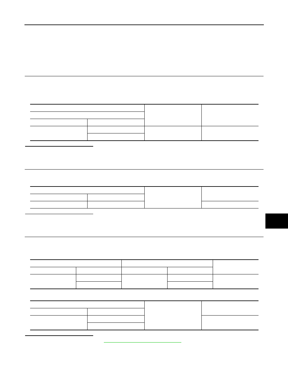
Check voltage between sunroof motor assembly harness connector and ground.
Is the inspection result normal?
YES
>> GO TO 2.
NO
>> GO TO 3.
2.
CHECK GROUND CIRCUIT
1.
Turn ignition switch OFF.
2.
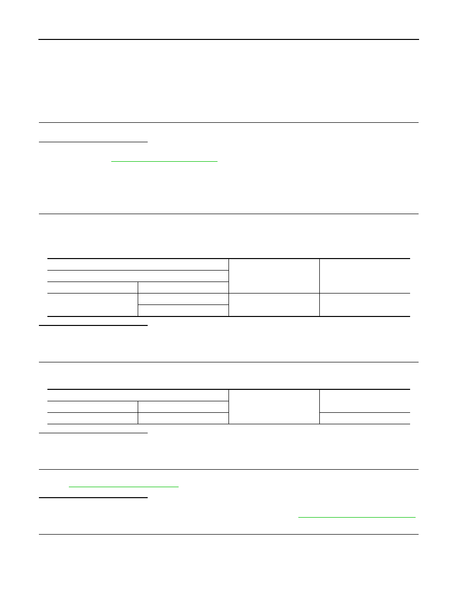
Check continuity between sunroof motor assembly harness connector and ground.
Is the inspection result normal?
YES
>> INSPECTION END
NO
>> Repair or replace harness.
3.
CHECK SUNROOF MOTOR CIRCUIT
1.
Turn ignition switch OFF.
2.
Disconnect BCM connector.
3.
Check continuity between BCM harness connector and sunroof motor assembly harness connector.
4.
Check continuity between BCM harness connector and ground.
Is the inspection result normal?
YES
>> Replace BCM. Refer to
BCS-83, "Removal and Installation"
NO
>> Repair or replace harness.
(+)
(–)
Voltage (V)
(Approx.)
Sunroof motor assembly
Connector
Terminal
R4
9
Ground
Battery voltage
7
Sunroof motor assembly
Ground
Continuity
Connector
Terminal
R4
10
Existed
BCM
Sunroof motor assembly
Continuity
Connector
Terminal
Connector
Terminal
M118
2
R4
7
Existed
3
9
BCM
Ground
Continuity
Connector
Terminal
M118
2
Not existed
3
RF-10
< DTC/CIRCUIT DIAGNOSIS >
SUNROOF SWITCH
SUNROOF SWITCH
Description
INFOID:0000000005248618
Tilt up/down and slide open/close by sunroof switch operation.
Component Function Check
INFOID:0000000005248619
1.
CHECK SUNROOF MOTOR OPERATION
Check tilt up/down and slide open/close operations using sunroof switch.
Is the inspection result normal?
YES
>> Sunroof switch is OK.
NO
>> Refer to
.
Diagnosis Procedure
INFOID:0000000005248620
SUNROOF SWITCH
1.
CHECK SUNROOF SWITCH POWER SUPPLY CIRCUIT
1.
Turn ignition switch OFF.
2.
Disconnect sunroof switch connector.
3.
Turn ignition switch ON.
4.
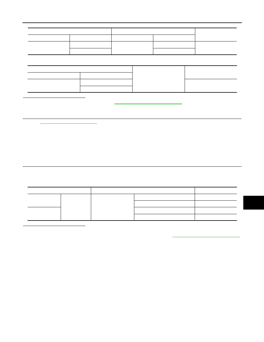
Check voltage between sunroof switch harness connector and ground.
Is the inspection result normal?
YES
>> GO TO 2.
NO
>> GO TO 4.
2.
CHECK GROUND CIRCUIT
1.
Turn ignition switch OFF.
2.
Check continuity between sunroof switch harness connector and ground.
Is the inspection result normal?
YES
>> GO TO 3.
NO
>> Repair or replace harness.
3.
CHECK SUNROOF SWITCH
Check sunroof switch.
Refer to
Is the inspection result normal?
YES
>> GO TO 5.
NO
>> Replace sunroof switch (built in map lamp assembly). Refer to
RF-83, "Removal and Installation"
.
4.
CHECK SUNROOF SWITCH CIRCUIT
1.
Turn ignition switch OFF.
2.
Disconnect sunroof motor assembly connector.
3.
Check continuity between sunroof switch assembly harness connector and sunroof switch harness con-
nector.
(+)
(–)
Voltage (V)
(Approx.)
Sunroof switch
Connector
Terminal
R16
1
Ground
Battery voltage
3
Sunroof switch
Ground
Continuity
Connector
Terminal
R16
2
Existed
SUNROOF SWITCH
RF-11
< DTC/CIRCUIT DIAGNOSIS >
C
D
E
F
G
H
I
J
L
M
A
B
RF
N
O
P
4.
Check continuity between sunroof switch assembly harness connector and ground.
Is the inspection result normal?
YES
>> Replace sunroof motor assembly.
RF-75, "Removal and Installation"
NO
>> Repair or replace harness.
5.
CHECK INTERMITTENT INCIDENT
GI-36, "Intermittent Incident"
.
>> INSPECTION END
Component Inspection
INFOID:0000000005248621
SUNROOF SWITCH
1.
CHECK SUNROOF SWITCH
1.
Turn ignition switch OFF.
2.
Disconnect sunroof switch connector.
3.
Check continuity between sunroof switch terminals.
Is the inspection result normal?
YES
>> INSPECTION END
NO
>> Replace sunroof switch (built in map lamp assembly). Refer to
RF-83, "Removal and Installation"
.
Sunroof switch
Sunroof motor assembly
Continuity
Connector
Terminal
Connector
Terminal
R16
1
R4
5
Existed
3
1
Sunroof motor assembly
Ground
Continuity
Connector
Terminal
R4
5
Not existed
1
Terminals
Condition
Continuity
1
2
Sunroof switch
TILT the DOWN/SLIDE OPEN
Existed
Other than the above
Not existed
3
TILT UP/SLIDE the CLOSE
Existed
Other than the above
Not existed
RF-12
< DTC/CIRCUIT DIAGNOSIS >
DOOR SWITCH
DOOR SWITCH
Description
INFOID:0000000005248622
Detects door open/closed condition.
Component Function Check
INFOID:0000000005248623
1.
CHECK FUNCTION
Check door switches (“DOOR SW-DR”, “DOOR SW-AS”) in the “Data Monitor” mode using CONSULT-III.
Is the inspection result normal?
YES
>> Door switch is OK.
NO
>> Refer to
Diagnosis Procedure
INFOID:0000000005248624
1.
CHECK FRONT DOOR SWITCH INPUT SIGNAL
1.
Turn ignition switch OFF.
2.
Disconnect malfunctioning front door switch connector.
3.
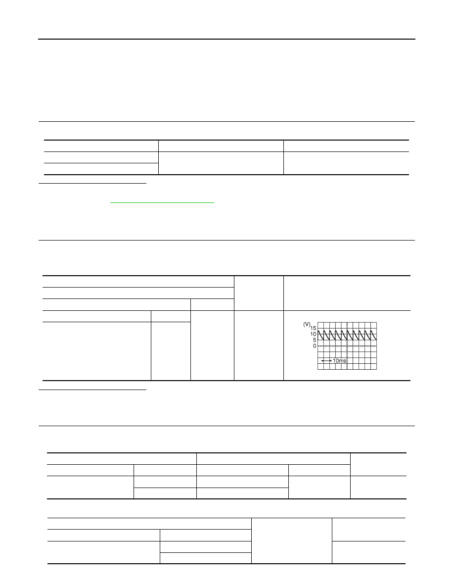
Check voltage signal between malfunctioning front door switch harness connector and ground.
Is the inspection result normal?
YES
>> GO TO 3.
NO
>> GO TO 2.
2.
CHECK DOOR SWITCH CIRCUIT
1.
Disconnect BCM connector.
2.
Check continuity between BCM harness connector and malfunctioning door switch harness connector.
3.
Check continuity between BCM harness connector and ground.
Monitor item
Door condition
Display
DOOR SW-DR
CLOSE
→
OPEN
OFF
→
ON
DOOR SW-AS
(+)
(–)
Voltage (V)
(Approx.)
Front door switch
Connector
Terminal
Driver side
B16
2
Ground
Passenger side
B216
JPMIA0594GB
BCM
Front door switch
Continuity
Connector
Terminal
Connector
Terminal
M123
124
B216
2
Existed
150
B16
BCM
Ground
Continuity
Connector
Terminal
M123
124
Not existed
150
Нет комментариевНе стесняйтесь поделиться с нами вашим ценным мнением.
Текст