Infiniti FX35, FX50 (S51). Manual — part 1556
SUNROOF SYSTEM
RF-5
< SYSTEM DESCRIPTION >
C
D
E
F
G
H
I
J
L
M
A
B
RF
N
O
P
SYSTEM DESCRIPTION
SUNROOF SYSTEM
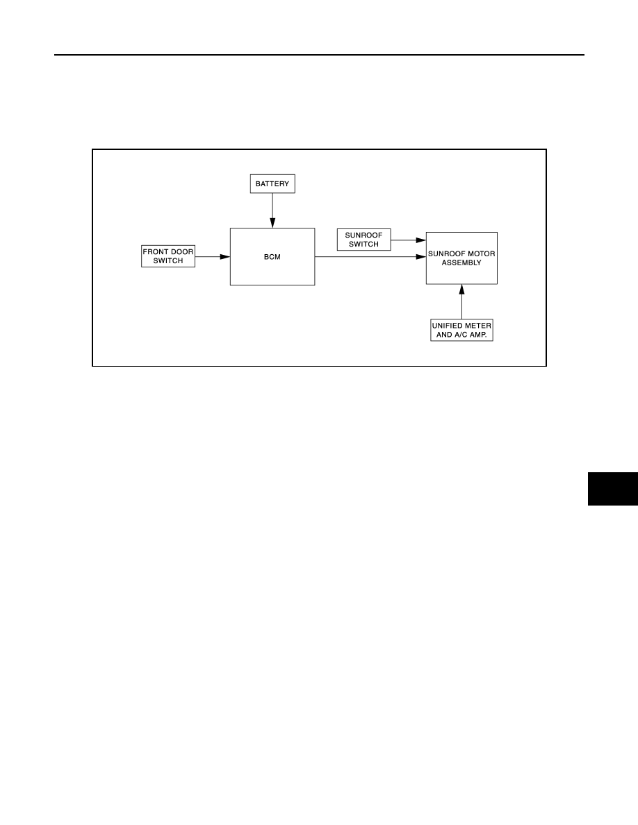
System Diagram
INFOID:0000000005248610
SUNROOF
System Description
INFOID:0000000005248611
SUNROOF OPERATION
• Sunroof motor assembly operates with the power supply that is output from BCM while ignition switch is ON
or retained power is operating.
• Tilt up/down and slide open/close signals from sunroof switch activates the sunroof motor to move arbitrarily.
• Sunroof motor assembly receives a vehicle speed signal from unified meter and A/C amp. and controls the
sunroof motor torque at the time of high speed operation.
AUTO OPERATION
Sunroof AUTO feature makes it possible to slide open and slide close or tilt up and tilt down the sunroof with-
out holding the sunroof switch in the slide open/tilt down or slide close/tilt up position.
RETAINED POWER OPERATION
Retained power operation is an additional power supply function that enables sunroof system to operate 45
seconds even after the ignition switch is turned OFF.
RETAINED POWER FUNCTION CANCEL CONDITIONS
• Front door CLOSE (door switch OFF)
→
OPEN (door switch ON).
• When ignition switch is ON again.
• When timer time passes. (45 seconds)
ANTI-PINCH FUNCTION
CAUTION:
There are some small distances immediately before the closed position that cannot detected.
The CPU of sunroof motor assembly monitors the sunroof condition by the signals from sunroof motor. When
sunroof motor assembly detects an interruption during close or tilt down operation, sunroof motor tilts up or
open [150 mm (5.91 in) or more] sunroof.
JMKIA2293GB
RF-6
< SYSTEM DESCRIPTION >
SUNROOF SYSTEM
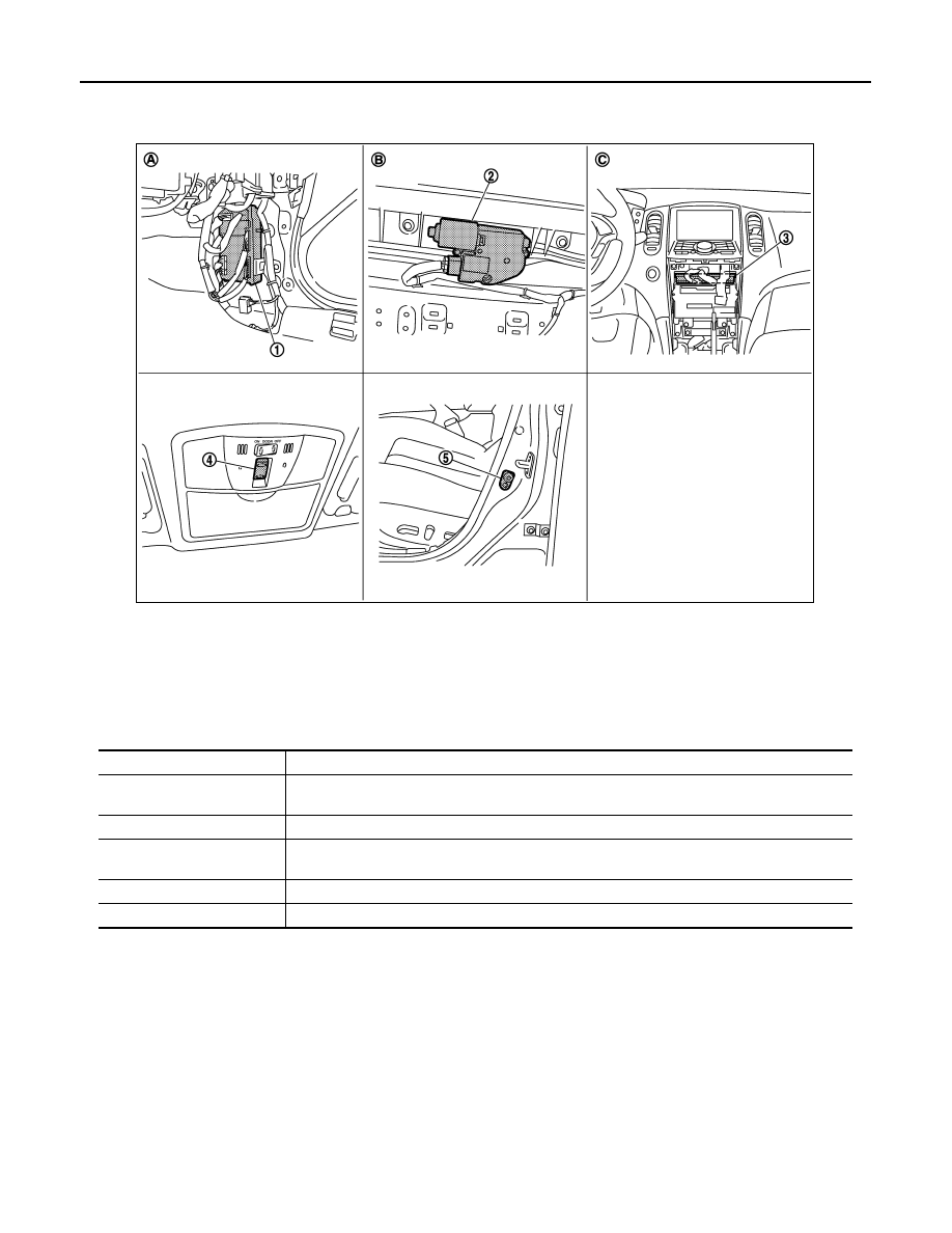
Component Parts Location
INFOID:0000000005248612
Component Description
INFOID:0000000005248613
1.
BCM
2.
Sunroof motor assembly
3.
Unified meter and A/C amp.
4.
Sunroof switch
5.
Front door switch (driver side)
A.
Dash side lower (passenger side)
B.
View with headlining removed
C.
Behind cluster lid C
JMKIA2669ZZ
Component
Function
BCM
• Supplies the power to sunroof motor assembly.
• Controls retained power.
Sunroof switch
Transmits tilt up/down and slides open/close operation signal to sunroof motor assembly.
Sunroof motor assembly
It is sunroof motor and CPU integrated type that enables tilt up/down and slide open/close by
sunroof switch operation
Front door switch
Detects door open/close condition and transmits to BCM.
Unified meter and A/C amp.
Transmits vehicle speed signal to sunroof motor assembly.

DIAGNOSIS SYSTEM (BCM)
RF-7
< SYSTEM DESCRIPTION >
C
D
E
F
G
H
I
J
L
M
A
B
RF
N
O
P
DIAGNOSIS SYSTEM (BCM)
COMMON ITEM
COMMON ITEM : CONSULT-III Function (BCM - COMMON ITEM)
INFOID:0000000005248614
APPLICATION ITEM
CONSULT-III performs the following functions via CAN communication with BCM.
SYSTEM APPLICATION
BCM can perform the following functions for each system.
NOTE:
It can perform the diagnosis modes except the following for all sub system selection items.
×
: Applicable item
NOTE:
*: This item is displayed, but is not used.
FREEZE FRAME DATA (FFD)
The BCM records the following vehicle condition at the time a particular DTC is detected, and displays on
CONSULT-III.
Diagnosis mode
Function Description
Work Support
Changes the setting for each system function.
Self Diagnostic Result
Displays the diagnosis results judged by BCM.
CAN Diag Support Monitor
Monitors the reception status of CAN communication viewed from BCM. Refer to CONSULT-III opera-
tion manual.
Data Monitor
The BCM input/output signals are displayed.
Active Test
The signals used to activate each device are forcibly supplied from BCM.
Ecu Identification
The BCM part number is displayed.
Configuration
• Read and save the vehicle specification.
• Write the vehicle specification when replacing BCM.
System
Sub system selection item
Diagnosis mode
Work Support
Data Monitor
Active Test
Door lock
DOOR LOCK
×
×
×
Rear window defogger
REAR DEFOGGER
×
×
Warning chime
BUZZER
×
×
Interior room lamp timer
INT LAMP
×
×
×
Exterior lamp
HEAD LAMP
×
×
×
Wiper and washer
WIPER
×
×
×
Turn signal and hazard warning lamps
FLASHER
×
×
×
—
AIR CONDITONER*
• Intelligent Key system
• Engine start system
INTELLIGENT KEY
×
×
×
Combination switch
COMB SW
×
Body control system
BCM
×
IVIS - NATS
IMMU
×
×
Interior room lamp battery saver
BATTERY SAVER
×
×
×
Back door open
TRUNK
×
×
Vehicle security system
THEFT ALM
×
×
×
RAP system
RETAINED PWR
×
Signal buffer system
SIGNAL BUFFER
×
×

RF-8
< SYSTEM DESCRIPTION >
DIAGNOSIS SYSTEM (BCM)
RETAINED PWR
RETAINED PWR : CONSULT-III Function (BCM - RETAINED PWR)
INFOID:0000000005248615
Data monitor
CONSULT screen item
Indication/Unit
Description
Vehicle Speed
km/h
Vehicle speed of the moment a particular DTC is detected
Odo/Trip Meter
km
Total mileage (Odometer value) of the moment a particular DTC is detected
Vehicle Condition
SLEEP>LOCK
Power position status of
the moment a particular
DTC is detected
While turning BCM status from low power consumption mode to
normal mode (Power supply position is “LOCK”)
SLEEP>OFF
While turning BCM status from low power consumption mode to
normal mode (Power supply position is “OFF”.)
LOCK>ACC
While turning power supply position from “LOCK” to “ACC”
ACC>ON
While turning power supply position from “ACC” to “IGN”
RUN>ACC
While turning power supply position from “RUN” to “ACC” (Vehicle
is stopping and selector lever is except P position.)
CRANK>RUN
While turning power supply position from “CRANKING” to “RUN”
(From cranking up the engine to run it)
RUN>URGENT
While turning power supply position from “RUN“ to “ACC” (Emer-
gency stop operation)
ACC>OFF
While turning power supply position from “ACC” to “OFF”
OFF>LOCK
While turning power supply position from “OFF” to “LOCK”
OFF>ACC
While turning power supply position from “OFF” to “ACC”
ON>CRANK
While turning power supply position from “IGN” to “CRANKING”
OFF>SLEEP
While turning BCM status from normal mode (Power supply posi-
tion is “OFF”.) to low power consumption mode
LOCK>SLEEP
While turning BCM status from normal mode (Power supply posi-
tion is “LOCK”.) to low power consumption mode
LOCK
Power supply position is “LOCK” (Ignition switch OFF with steer-
ing is locked.)
OFF
Power supply position is “OFF” (Ignition switch OFF with steering
is unlocked.)
ACC
Power supply position is “ACC” (Ignition switch ACC)
ON
Power supply position is “IGN” (Ignition switch ON with engine
stopped)
ENGINE RUN
Power supply position is “RUN” (Ignition switch ON with engine
running)
CRANKING
Power supply position is “CRANKING” (At engine cranking)
IGN Counter
0 - 39
The number of times that ignition switch is turned ON after DTC is detected
• The number is 0 when a malfunction is detected now.
• The number increases like 1
→
2
→
3...38
→
39 after returning to the normal condition
whenever ignition switch OFF
→
ON.
• The number is fixed to 39 until the self-diagnosis results are erased if it is over 39.
Monitor Item
Description
DOOR SW-DR
Indicates [ON/OFF] condition of driver side door switch.
DOOR SW-AS
Indicates [ON/OFF] condition of passenger side door switch.
Нет комментариевНе стесняйтесь поделиться с нами вашим ценным мнением.
Текст