Infiniti FX35, FX50 (S51). Manual — part 548
POWER SUPPLY AND GROUND CIRCUIT
DLN-27
< DTC/CIRCUIT DIAGNOSIS >
[TRANSFER: ETX13C]
C
E
F
G
H
I
J
K
L
M
A
B
DLN
N
O
P
POWER SUPPLY AND GROUND CIRCUIT
Description
INFOID:0000000005249070
Supplies power to AWD control unit.
Diagnosis Procedure
INFOID:0000000005249071
1.
CHECK AWD CONTROL UNIT POWER SUPPLY (1)
1.
Turn the ignition switch OFF.
2.
Disconnect AWD control unit harness connector.
3.
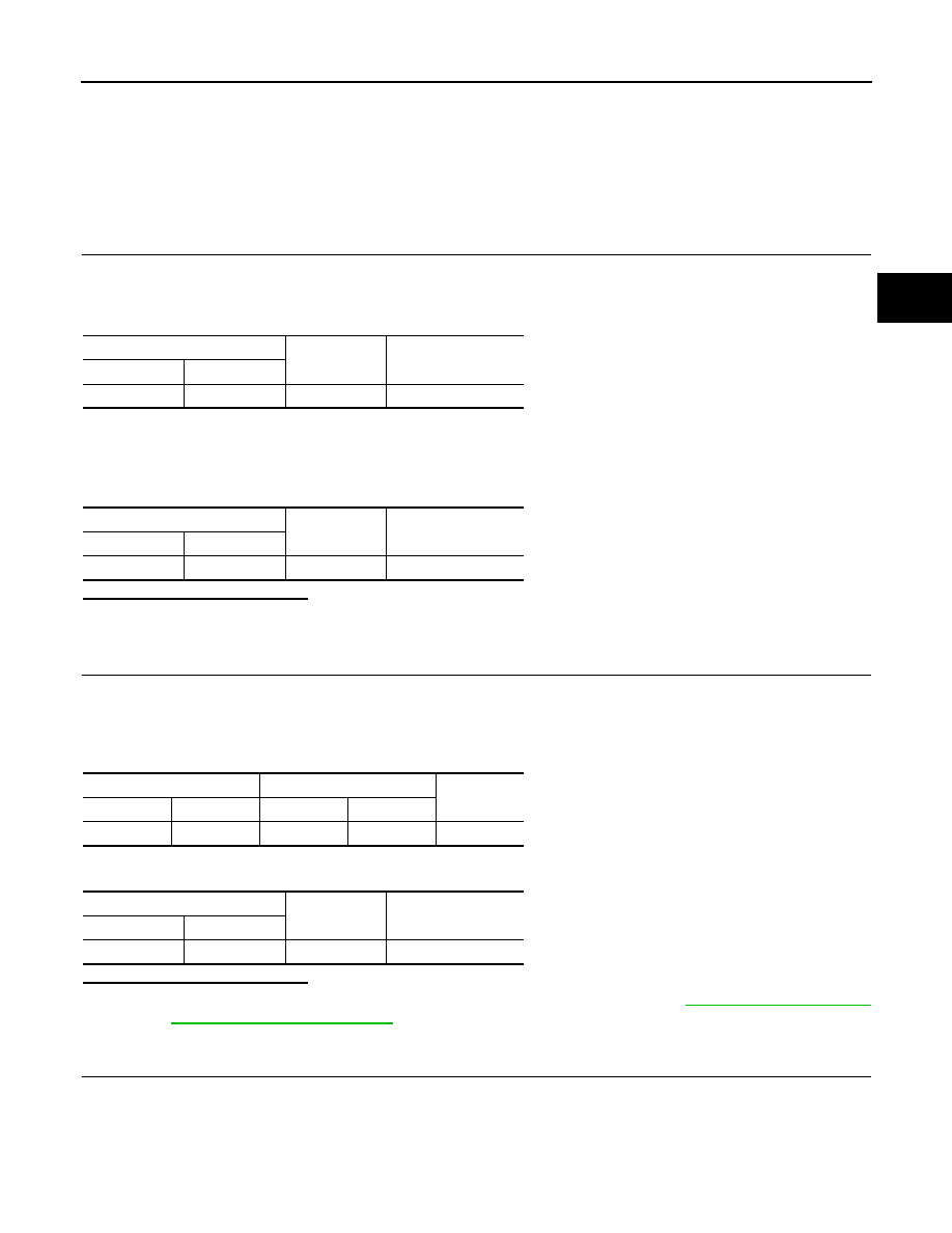
Check the voltage between AWD control unit harness connector and ground.
4.
Turn the ignition switch ON.
CAUTION:
Never start the engine.
5.
Check the voltage between AWD control unit harness connector and ground.
Is the inspection result normal?
YES
>> GO TO 3.
NO
>> GO TO 2.
2.
CHECK AWD CONTROL UNIT POWER SUPPLY (2)
1.
Turn the ignition switch OFF.
2.
Check the 10A fuse (#45).
3.
Disconnect IPDM E/R harness connector.
4.
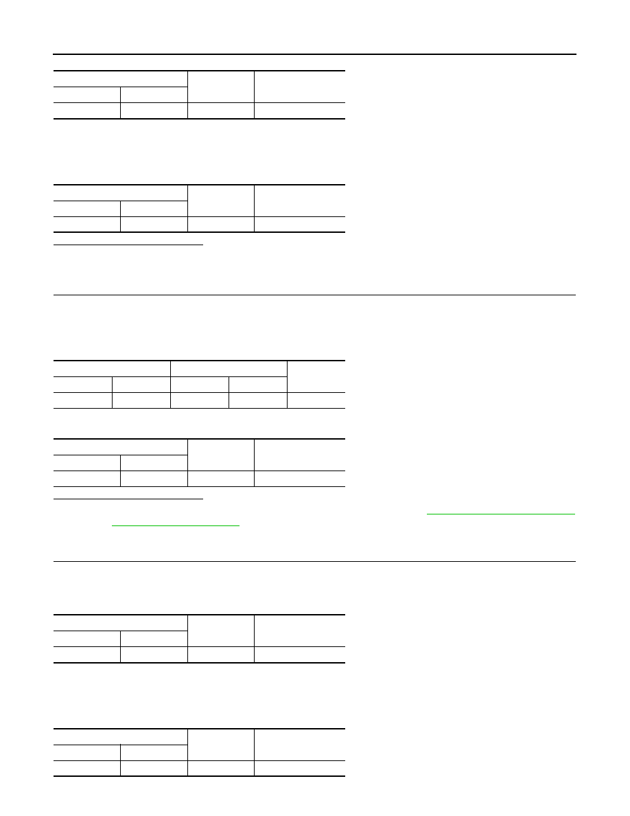
Check the continuity between AWD control unit harness connector and IPDM E/R harness connector.
5.
Check the continuity between AWD control unit harness connector and the ground.
Is the inspection result normal?
YES
>> Perform the trouble diagnosis for ignition power supply circuit. Refer to
NO
>> Repair or replace error-detected parts.
3.
CHECK AWD CONTROL UNIT POWER SUPPLY (3)
1.
Turn the ignition switch OFF.
2.
Check the voltage between AWD control unit harness connector and ground.
AWD control unit
—
Voltage (Approx.)
Connector
Terminal
M105
7
Ground
0 V
AWD control unit
—
Voltage
Connector
Terminal
M105
7
Ground
Battery voltage
AWD control unit
IPDM E/R
Continuity
Connector
Terminal
Connector
Terminal
M105
7
E5
25
Existed
AWD control unit
—
Continuity
Connector
Terminal
M105
7
Ground
Not existed
DLN-28
< DTC/CIRCUIT DIAGNOSIS >
[TRANSFER: ETX13C]
POWER SUPPLY AND GROUND CIRCUIT
3.
Turn the ignition switch ON.
CAUTION:
Never start the engine.
4.
Check the voltage between AWD control unit harness connector and ground.
Is the inspection result normal?
YES
>> GO TO 5.
NO
>> GO TO 4.
4.
CHECK AWD CONTROL UNIT POWER SUPPLY (4)
1.
Turn the ignition switch OFF.
2.
Check the 10A fuse (#11).
3.
Disconnect fuse block (J/B) harness connector.
4.
Check the continuity between AWD control unit harness connector and fuse block (J/B).
5.
Check the continuity between AWD control unit harness connector and the ground.
Is the inspection result normal?
YES
>> Perform the trouble diagnosis for power supply circuit. Refer to
NO
>> Repair or replace error-detected parts.
5.
CHECK AWD SOLENOID POWER SUPPLY (1)
1.
Turn the ignition switch OFF.
2.
Disconnect AWD solenoid harness connector.
3.
Check the voltage between AWD control unit harness connector and ground.
4.
Turn the ignition switch ON.
CAUTION:
Never start the engine.
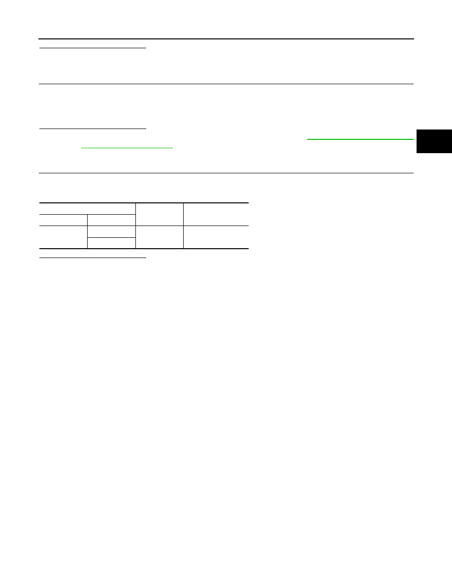
5.
Check the voltage between AWD control unit harness connector and ground.
AWD control unit
—
Voltage (Approx.)
Connector
Terminal
M105
15
Ground
Battery voltage
AWD control unit
—
Voltage
Connector
Terminal
M105
15
Ground
Battery voltage
AWD control unit
Fuse block (J/B)
Continuity
Connector
Terminal
Connector
Terminal
M105
15
M1
1A
Existed
AWD control unit
—
Continuity
Connector
Terminal
M105
15
Ground
Not existed
AWD control unit
—
Voltage
Connector
Terminal
M105
9
Ground
Battery voltage
AWD control unit
—
Voltage
Connector
Terminal
M105
9
Ground
Battery voltage
POWER SUPPLY AND GROUND CIRCUIT
DLN-29
< DTC/CIRCUIT DIAGNOSIS >
[TRANSFER: ETX13C]
C
E
F
G
H
I
J
K
L
M
A
B
DLN
N
O
P
Is the inspection result normal?
YES
>> GO TO 7.
NO
>> GO TO 6.
6.
CHECK AWD SOLENOID POWER SUPPLY (2)
1.
Turn the ignition switch OFF.
2.
Check the 10A fuse (#33).
3.
Check the harness for open or short between AWD control unit harness connector No.9 terminal and fuse
box.
Is the inspection result normal?
YES
>> Perform the trouble diagnosis for power supply circuit. Refer to
NO
>> Repair or replace error-detected parts.
7.
CHECK AWD CONTROL UNIT GROUND
1.
Turn the ignition switch OFF.
2.
Check the continuity between AWD control unit harness connector and ground.
Is the inspection result normal?
YES
>> INSPECTION END
NO
>> Repair or replace error-detected parts.
AWD control unit
—
Continuity
Connector
Terminal
M105
10
Ground
Existed
11
DLN-30
< DTC/CIRCUIT DIAGNOSIS >
[TRANSFER: ETX13C]
AWD WARNING LAMP
AWD WARNING LAMP
Description
INFOID:0000000005249072
• Turns ON when there is a malfunction in AWD system. AWD warning lamp indicates the vehicle is in fail-safe
mode and shifting to rear-wheel drive or 4-wheel drive (front-wheels still have some driving torque).
• Also turns ON when ignition switch is turned ON, for the purpose of lamp check. Turns OFF approximately
for 1 second after the engine starts if system is normal.
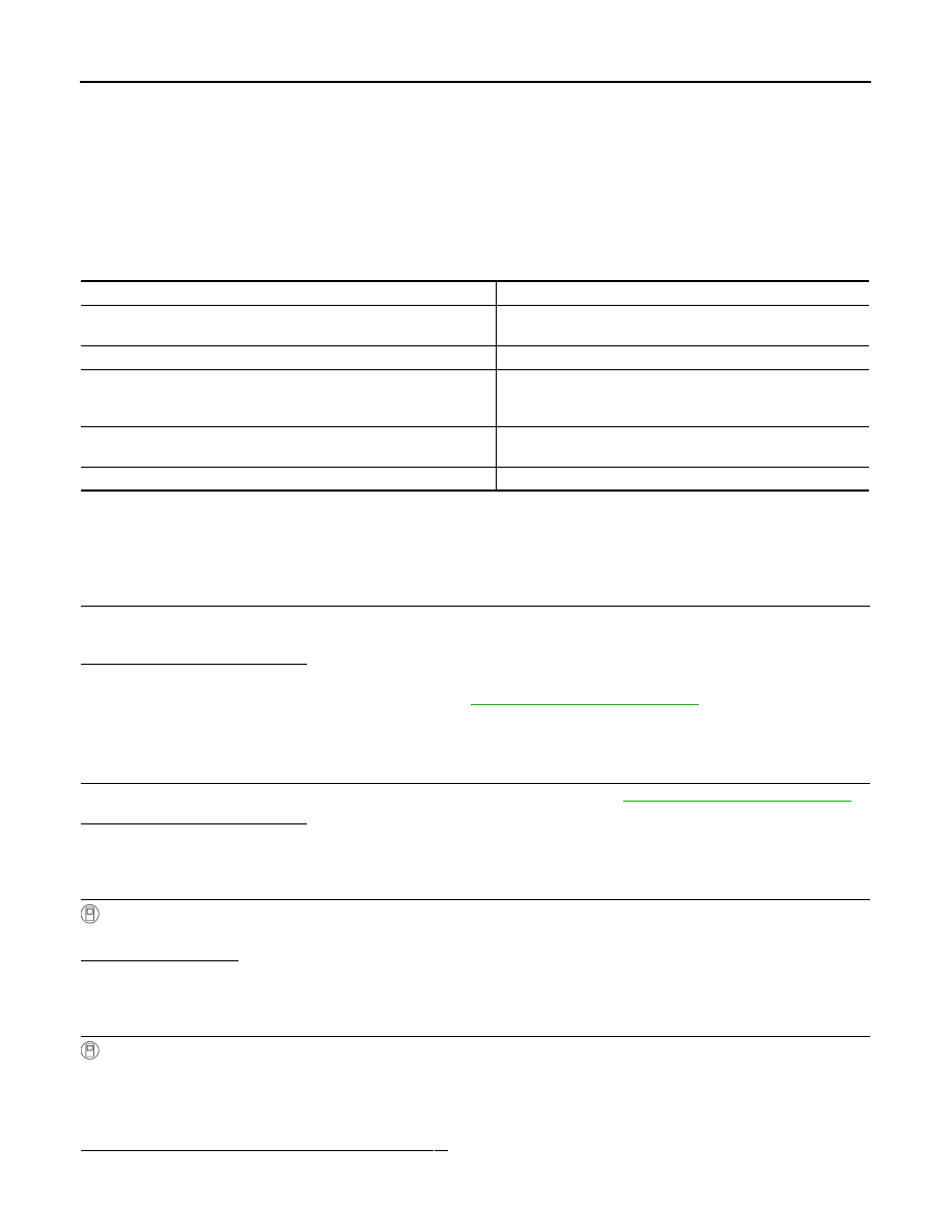
AWD WARNING LAMP INDICATION
CAUTION:
• AWD warning lamp also turns ON due to data reception error, CAN communication error etc.
Component Function Check
INFOID:0000000005249073
1.
CHECK AWD WARNING LAMP FUNCTION
1.
Turn the ignition switch ON.
2.
Make sure that AWD warning lamp lights up.
Is the inspection result normal?
YES
>> INSPECTION END
NO
>> Proceed to diagnosis procedure. Refer to
Diagnosis Procedure
INFOID:0000000005249074
1.
CHECK POWER SUPPLY AND GROUND CIRCUIT
Perform the trouble diagnosis for power supply and ground circuit. Refer to
Is the inspection result normal?
YES
>> GO TO 2.
NO
>> Repair or replace the error-detected parts.
2.
PERFORM SELF-DIAGNOSIS
With CONSULT-III
Perform self-diagnosis for “ALL MODE AWD/4WD”.
Is any DTC detected?
YES
>> Check the DTC.
NO
>> GO TO 3.
3.
CHECK AWD WARNING LAMP SIGNAL
With CONSULT-III
1.
Turn the ignition switch ON.
CAUTION:
Never start the engine.
2.
Check “4WD WARN LAMP” of CONSULT-III “DATA MONITOR” for “ALL MODE AWD/4WD”.
Does the item on “DATA MONITOR” indicate “On”?
YES
>> GO TO 4.
Condition
AWD warning lamp
Lamp check
Turns ON when ignition switch is turned ON. Turns OFF ap-
prox. 1 second after the engine start.
AWD system malfunction
ON
Protection function is activated due to heavy load to electric controlled
coupling. (AWD system is not malfunctioning and AWD system chang-
es to rear wheel drive.)
Quick blinking: 2 times/second
(Blinking in approx. 1 minute and then turning OFF)
Large difference in diameter of front/rear tires
Slow blinking: 1 time/2 seconds
(Continuing to blink until turning ignition switch OFF)
Other than above (system normal)
OFF
Нет комментариевНе стесняйтесь поделиться с нами вашим ценным мнением.
Текст