Infiniti FX35, FX50 (S51). Manual — part 547
P1826 TRANSFER FLUID TEMPERATURE
DLN-23
< DTC/CIRCUIT DIAGNOSIS >
[TRANSFER: ETX13C]
C
E
F
G
H
I
J
K
L
M
A
B
DLN
N
O
P
Is the inspection result normal?
YES
>> GO TO 2.
NO
>> GO TO 3.
2.
CHECK TRANSFER FLUID TEMPERATURE SENSOR
Check the resistance between transfer fluid temperature sensor harness connector terminals. Refer to
Is the inspection result normal?
YES
>> GO TO 6.
NO
>> Replace transfer fluid temperature sensor. Refer to
DLN-88, "VQ35HR : Exploded View"
DLN-92, "VK50VE : Exploded View"
(VK50VE).
3.
CHECK TRANSFER FLUID TEMPERATURE SENSOR SIGNAL (2)
Check the voltage between AWD solenoid harness connector and ground.
Is the inspection result normal?
YES
>> GO TO 4.
NO
>> GO TO 5.
4.
CHECK AWD CONTROL UNIT GROUND
1.
Turn the ignition switch OFF.
2.
Disconnect AWD control unit harness connector.
3.
Check the continuity between AWD control unit harness connector and ground.
Is the inspection result normal?
YES
>> GO TO 5.
NO
>> Repair or replace error-detected parts.
5.
CHECK TRANSFER FLUID TEMPERATURE SENSOR CIRCUIT
1.
Turn the ignition switch OFF.
2.
Disconnect AWD control unit harness connector.
3.
Check the continuity between AWD control unit harness connector and AWD solenoid harness connector.
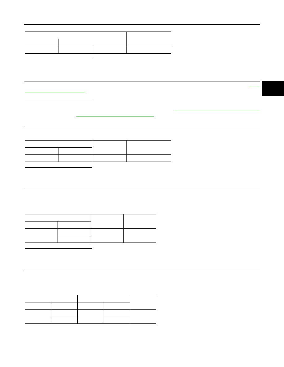
4.
Check the continuity between AWD control unit harness connector and the ground.
AWD solenoid
Voltage
(Approx.)
Connector
Terminal
F57
6
7
2.5 V
AWD solenoid
—
Voltage
(Approx.)
Connector
Terminal
F57
6
Ground
2.5 V
AWD control unit
—
Continuity
Connector
Terminal
M105
10
Ground
Existed
11
AWD control unit
AWD solenoid
Continuity
Connector
Terminal
Connector
Terminal
M105
13
F57
6
Existed
3
7
DLN-24
< DTC/CIRCUIT DIAGNOSIS >
[TRANSFER: ETX13C]
P1826 TRANSFER FLUID TEMPERATURE
Is the inspection result normal?
YES
>> GO TO 6.
NO
>> Repair or replace error-detected parts.
6.
CHECK TERMINALS AND HARNESS CONNECTORS
1.
Check AWD control unit pin terminals for damage or loose connection with harness connector.
2.
Check transfer fluid temperature sensor pin terminals for damage or loose connection with harness con-
nector.
Is the inspection result normal?
YES
>> Replace AWD control unit. Refer to
NO
>> Repair or replace error-detected parts.
Component Inspection
INFOID:0000000005249063
1.
CHECK TRANSFER FLUID TEMPERATURE SENSOR
1.
Turn ignition switch OFF.
2.
Disconnect AWD solenoid harness connector.
3.
Check resistance between AWD solenoid connector terminals.
Is inspection result normal?
YES
>> INSPECTION END
NO
>> Transfer fluid temperature sensor is malfunctioning. Replace electric controlled coupling. Refer to
DLN-88, "VQ35HR : Exploded View"
DLN-92, "VK50VE : Exploded View"
(VK50VE).
AWD control unit
—
Continuity
Connector
Terminal
M105
13
Ground
Not existed
3
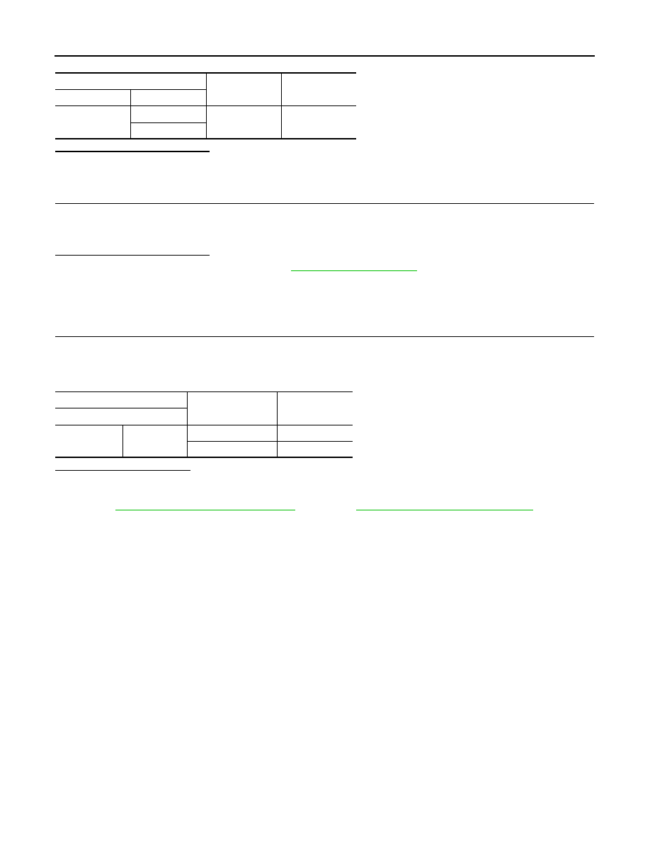
AWD solenoid
Condition
Resistance
(Approx.)
Terminal
6
7
20
°
C (68
°
F)
2.5 k
Ω
80
°
C (176
°
F)
0.3 k
Ω
U1000 CAN COMM CIRCUIT
DLN-25
< DTC/CIRCUIT DIAGNOSIS >
[TRANSFER: ETX13C]
C
E
F
G
H
I
J
K
L
M
A
B
DLN
N
O
P
U1000 CAN COMM CIRCUIT
Description
INFOID:0000000005249064
CAN (Controller Area Network) is a serial communication line for real time application. It is an on-vehicle mul-
tiplex communication line with high data communication speed and excellent error detection ability. Many elec-
tronic control units are equipped onto a vehicle, and each control unit shares information and links with other
control units during operation (not independent). In CAN communication, control units are connected with 2
communication lines (CAN-H line, CAN-L line) allowing a high rate of information transmission with less wiring.
Each control unit communicate data but selectively reads required data only.
DTC Logic
INFOID:0000000005249065
DTC DETECTION LOGIC
DTC CONFIRMATION PROCEDURE
1.
DTC REPRODUCTION PROCEDURE
With CONSULT-III
1.
Turn the ignition switch OFF to ON.
2.
Perform self-diagnosis for “ALL MODE AWD/4WD”.
Is DTC “U1000” detected?
YES
>> Proceed to diagnosis procedure. Refer to
NO
>> INSPECTION END
Diagnosis Procedure
INFOID:0000000005249066
1.
PERFORM SELF-DIAGNOSIS
With CONSULT-III
Perform self-diagnosis for “ALL MODE AWD/4WD”.
Is DTC “U1000” detected?
YES
>> CAN specification chart. Refer to
LAN-20, "Trouble Diagnosis Flow Chart"
NO
>> INSPECTION END
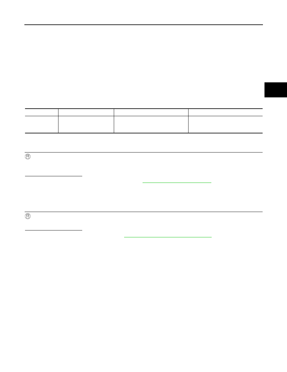
DTC
Display item
Malfunction detected condition
Possible cause
U1000
CAN COMM CIRCUIT
AWD control unit is not transmitting/re-
ceiving CAN communication signal for 2
seconds or more.
• CAN communication error
• Malfunction of AWD control unit
DLN-26
< DTC/CIRCUIT DIAGNOSIS >
[TRANSFER: ETX13C]
U1010 CONTROL UNIT (CAN)
U1010 CONTROL UNIT (CAN)
Description
INFOID:0000000005249067
CAN (Controller Area Network) is a serial communication line for real time application. It is an on-vehicle mul-
tiplex communication line with high data communication speed and excellent error detection ability. Many elec-
tronic control units are equipped onto a vehicle, and each control unit shares information and links with other
control units during operation (not independent). In CAN communication, control units are connected with 2
communication lines (CAN-H line, CAN-L line) allowing a high rate of information transmission with less wiring.
Each control unit communicate data but selectively reads required data only.
DTC Logic
INFOID:0000000005249068
DTC DETECTION LOGIC
DTC CONFIRMATION PROCEDURE
1.
DTC REPRODUCTION PROCEDURE
With CONSULT-III
1.
Turn the ignition switch OFF to ON.
2.
Perform self-diagnosis for “ALL MODE AWD/4WD”.
Is DTC “U1010” detected?
YES
>> Proceed to diagnosis procedure. Refer to
NO
>> INSPECTION END
Diagnosis Procedure
INFOID:0000000005249069
1.
CHECK AWD CONTROL UNIT
Check AWD control unit harness connector for disconnection and deformation.
Is the inspection result normal?
YES
>> Replace AWD control unit. Refer to
NO
>> Repair or replace error-detected parts.
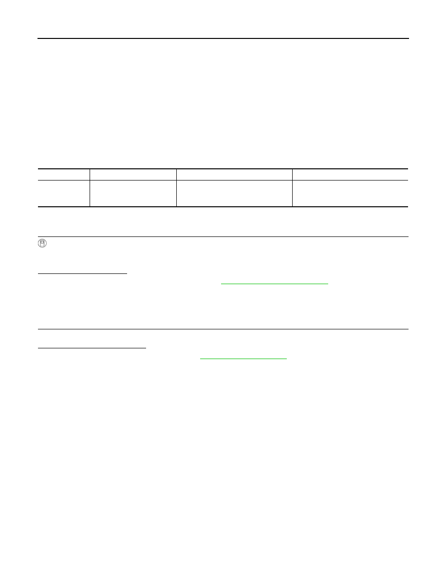
DTC
Display item
Malfunction detected condition
Possible cause
U1010
CONTROL UNIT (CAN)
Detecting error during the initial diagno-
sis of CAN controller of AWD control
unit.
Malfunction of AWD control unit
Нет комментариевНе стесняйтесь поделиться с нами вашим ценным мнением.
Текст