Infiniti FX35, FX50 (S51). Manual — part 1264
IP-24
< REMOVAL AND INSTALLATION >
CENTER CONSOLE ASSEMBLY
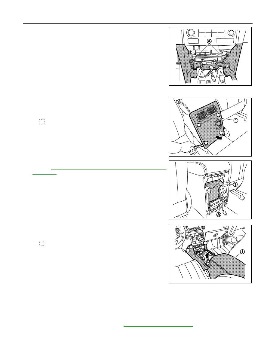
10. Remove center console assembly fixing screws (A).
11. Put front seat to front must position.
12. Remove console rear finisher.
• Pull back the console rear finisher (1) with remover tool (A).
• Disconnect harness connectors.
13. Remove rear ventilator duct (1).
Refer to
VTL-16, "REAR VENTILATOR DUCT 1 : Removal and
.
14. Remove center console fixing screws (A).
15. Remove center console assembly.
Pull back and lift up center console assembly (1).
INSTALLATION
Install in the reverse order of removal.
Disassembly and Assembly
INFOID:0000000005241043
DISASSEMBLY
1.
Remove center console assembly. Refer to
IP-22, "Removal and Installation"
JMJIA1977ZZ
: Metal clip
JMJIA1978ZZ
JMJIA1979ZZ
: Clip
JMJIA1980ZZ
CENTER CONSOLE ASSEMBLY
IP-25
< REMOVAL AND INSTALLATION >
C
D
E
F
G
H
I
K
L
M
A
B
IP
N
O
P
2.
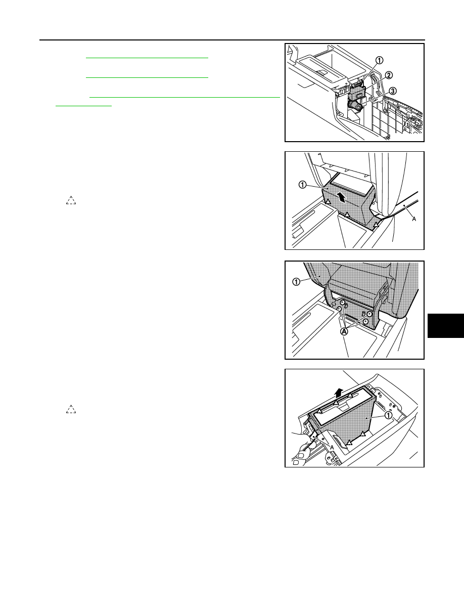
Remove USB connector (1).
Refer to
AV-151, "Removal and Installation"
.
3.
Remove auxiliary input jacks (2).
Refer to
AV-577, "Removal and Installation"
.
4.
Remove power outlet (3).
Refer to
PWO-12, "CONSOLE POWER SOCKET : Removal
5.
Remove console lid assembly.
• Open the console lid.
• Remove console hinge mask (1) fixing pawls with remover tool
(A).
• Remove console lid assembly (1) fixing screws (A), and then
remove console lid assembly.
6.
Remove DVD finisher (if equipped).
• Remove DVD finisher (1) fixing pawls with remover tool (A).
• Pull up DVD finisher.
7.
Remove DVD player (if equipped).
8.
Remove console box assembly.
JMJIA2002ZZ
: Pawl
JMJIA2003ZZ
JMJIA2004ZZ
: Pawl
JMJIA2005ZZ
IP-26
< REMOVAL AND INSTALLATION >
CENTER CONSOLE ASSEMBLY
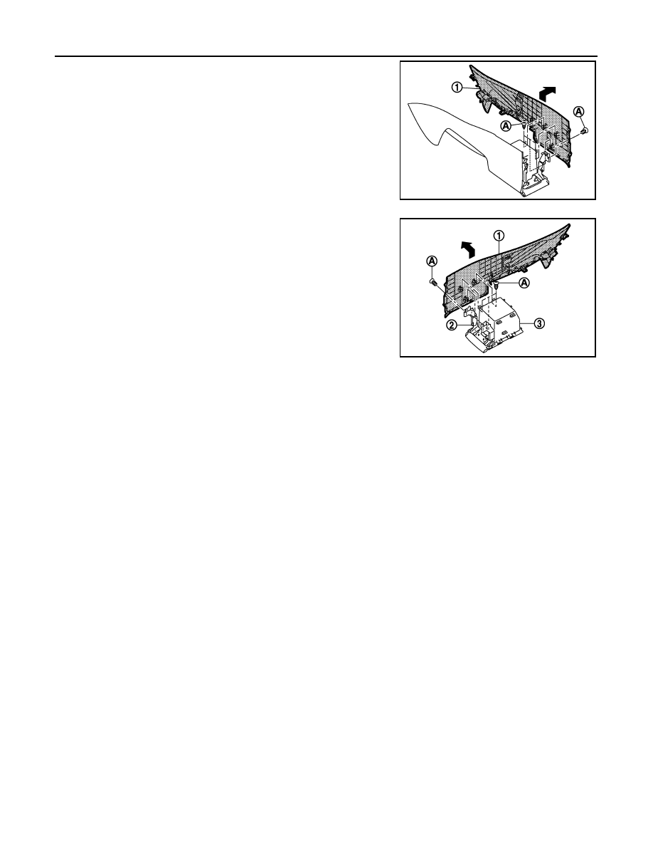
• Remove console pad LH.
- Remove console pad LH (1) fixing screws (A).
- Pull toward the arrow direction.
• Remove console pad RH.
- Remove console pad RH (1) fixing screws (A).
- Pull toward the arrow direction.
- Remove console rear bracket (2).
- Remove console box assembly (3).
ASSEMBLY
Assemble in the reverse order of disassembly.
JMJIA2006ZZ
JMJIA2007ZZ
LAN
LAN-1
ELECTRICAL & POWER CONTROL
C
D
E
F
G
H
I
J
K
L
B
SECTION
LAN
A
O
P
N
CONTENTS
LAN SYSTEM
CAN FUNDAMENTAL
PRECAUTION . . . . . . . . . . . ...
PRECAUTIONS . . . . . . . . . . . . ...
Precautions for Trouble Diagnosis . . . . . . ....
Precautions for Harness Repair . . . . . . . ....
SYSTEM DESCRIPTION . . . . . . . .
CAN COMMUNICATION SYSTEM . . . . .
System Description . . . . . . . . . . . . .
System Diagram . . . . . . . . . . . . . ..
CAN Communication Control Circuit . . . . . ...
DIAG ON CAN . . . . . . . . . . . . .
Description . . . . . . . . . . . . . . . ..
System Diagram . . . . . . . . . . . . . ..
TROUBLE DIAGNOSIS . . . . . . . . . .
Condition of Error Detection . . . . . . . . .
Symptom When Error Occurs in CAN Communi-
cation System . . . . . . . . . . . . . . ..
CAN Diagnosis with CONSULT-III . . . . . . ..
Self-Diagnosis . . . . . . . . . . . . . . .
CAN Diagnostic Support Monitor . . . . . . .
How to Use CAN Communication Signal Chart . ..
BASIC INSPECTION . . . . . . . . ...
DIAGNOSIS AND REPAIR WORKFLOW . . .
Trouble Diagnosis Flow Chart . . . . . . . . .
Trouble Diagnosis Procedure . . . . . . . . ..
CAN
HOW TO USE THIS MANUAL . . . . . .
HOW TO USE THIS SECTION . . . . . . ...
Caution . . . . . . . . . . . . . . . . .
Abbreviation List . . . . . . . . . . . . . ..
PRECAUTION . . . . . . . . . . . ..
PRECAUTIONS . . . . . . . . . . . . .
Precautions for Trouble Diagnosis . . . . . . ..
Precautions for Harness Repair . . . . . . . ..
BASIC INSPECTION . . . . . . . . ...
DIAGNOSIS AND REPAIR WORKFLOW . .
Interview Sheet . . . . . . . . . . . . . .
SYSTEM DESCRIPTION . . . . . . . .
CAN COMMUNICATION SYSTEM . . . . ...
CAN System Specification Chart . . . . . . . .
CAN Communication Signal Chart . . . . . . ..
DTC/CIRCUIT DIAGNOSIS . . . . . . .
CAN COMMUNICATION SYSTEM . . . . ...
Component Parts Location . . . . . . . . . ..
Wiring Diagram - CAN SYSTEM (WITH ACTIVE
AFS) - . . . . . . . . . . . . . . . . . ..
Wiring Diagram - CAN SYSTEM (WITHOUT AC-
TIVE AFS) - . . . . . . . . . . . . . . . .
MALFUNCTION AREA CHART . . . . . .
System Diagram . . . . . . . . . . . . . ..
CAN Communication Circuit . . . . . . . . .
ITS Communication Circuit . . . . . . . . . ..
MAIN LINE BETWEEN DLC AND M&A CIR-
CUIT . . . . . . . . . . . . . . . . ..
Diagnosis Procedure . . . . . . . . . . . ...
MAIN LINE BETWEEN M&A AND ADP CIR-
CUIT . . . . . . . . . . . . . . . . ..
Diagnosis Procedure . . . . . . . . . . . ...
MAIN LINE BETWEEN ADP AND CGW CIR-
CUIT . . . . . . . . . . . . . . . . ..
Нет комментариевНе стесняйтесь поделиться с нами вашим ценным мнением.
Текст