Infiniti FX35, FX50 (S51). Manual — part 1262
IP-16
< REMOVAL AND INSTALLATION >
INSTRUMENT PANEL ASSEMBLY
• Remove skirt clips of steering column lower cover (2).
• Release data link connector (pawl) then remove it from instrument lower panel LH.
• Disconnect harness connectors and aspirator duct.
19. Remove front body side welt LH. Refer to
INT-17, "Removal and Installation"
.
20. Remove instrument side finisher LH.
Pull back instrument side finisher LH (1).
21. Remove front pillar garnish LH. Refer to
INT-17, "Removal and Installation"
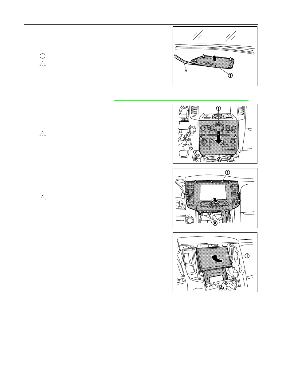
22. Remove speaker grille LH.
• Remove speaker grille LH (1) fixing pawls with remover tool
(A).
• Pull up and back speaker grille LH (1).
23. Remove front squawker. Refer to
24. Remove steering wheel. Refer to
ST-17, "Removal and Installation"
.
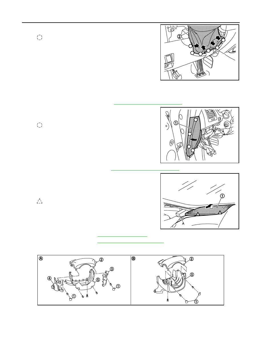
25. Remove steering column covers.
• Remove steering column mask (1) and then remove steering column cover fixing screws.
: Clip
JMJIA2008ZZ
: Clip
JMJIA1982ZZ
: Pawl
JMJIA1983ZZ
(A)
Column cover (with PADDLE SHIFTER)
(B)
Column cover (without PADDLE SHIFTER)
JMJIA1984ZZ
INSTRUMENT PANEL ASSEMBLY
IP-17
< REMOVAL AND INSTALLATION >
C
D
E
F
G
H
I
K
L
M
A
B
IP
N
O
P
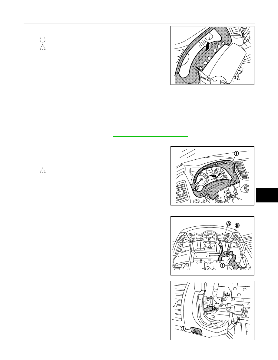
• Remove skirt clips and pawls of cluster lid A (6).
• Pull up steering column upper cover (2), and then remove steering column upper cover.
• Remove steering column side cover RH (3) fixing pawls and then remove steering column side cover
RH. (with PADDLE SHIFTER)
• Pull the steering column side cover LH (4) to the left side. (with PADDLE SHIFTER)
• Disconnect ADP steering switch connector. (with ADP)
• Remove steering column lower cover (5) fixing screws.
• Pull down steering column lower cover and then remove steering column lower cover.
26. Remove combination switch. Refer to
BCS-84, "Removal and Installation"
27. Remove paddle switch LH/RH (with PADDLE SHIFTER). Refer to
28. Remove cluster lid A.
• Pull back cluster lid A (1), and disengage pawls.
• Remove cluster lid A.
29. Remove combination meter. Refer to
.
30. Disconnect harness connector (A).
31. Remove instrument harness (1) fixing clip (B).
32. Disconnect trip A/B reset switch (1) harness connector (A).
.
: Clip
: Pawl
JMJIA2009ZZ
: Pawl
JMJIA1985ZZ
JMJIA1986ZZ
JMJIA1987ZZ
IP-18
< REMOVAL AND INSTALLATION >
INSTRUMENT PANEL ASSEMBLY
33. Remove center speaker grille.
• Disengage center speaker grille (1) fixing clips and pawls with
remover tool (A).
• Pull up center speaker grille.
34. Remove center speaker. Refer to
35. Remove inside key antenna. Refer to
DLK-281, "INSTRUMENT CENTER : Removal and Installation"
.
36. Remove cluster lid C.
• Remove cluster lid C (1) fixing screws (A).
• Pull down and back cluster lid C.
• Disconnect harness connectors.
37. Remove cluster lid D.
• Remove cluster lid D (1) fixing screws (A).
• Pull back cluster lid D.
• Disconnect harness connectors.
38. Remove display unit.
• Remove display unit (1) fixing screws (A).
• Pull toward the arrow direction.
• Disconnect harness connectors.
: Clip
: Pawl
JMJIA1988ZZ
: Pawl
JMJIA1989ZZ
: Pawl
JMJIA1990ZZ
JMJIA1991ZZ
INSTRUMENT PANEL ASSEMBLY
IP-19
< REMOVAL AND INSTALLATION >
C
D
E
F
G
H
I
K
L
M
A
B
IP
N
O
P
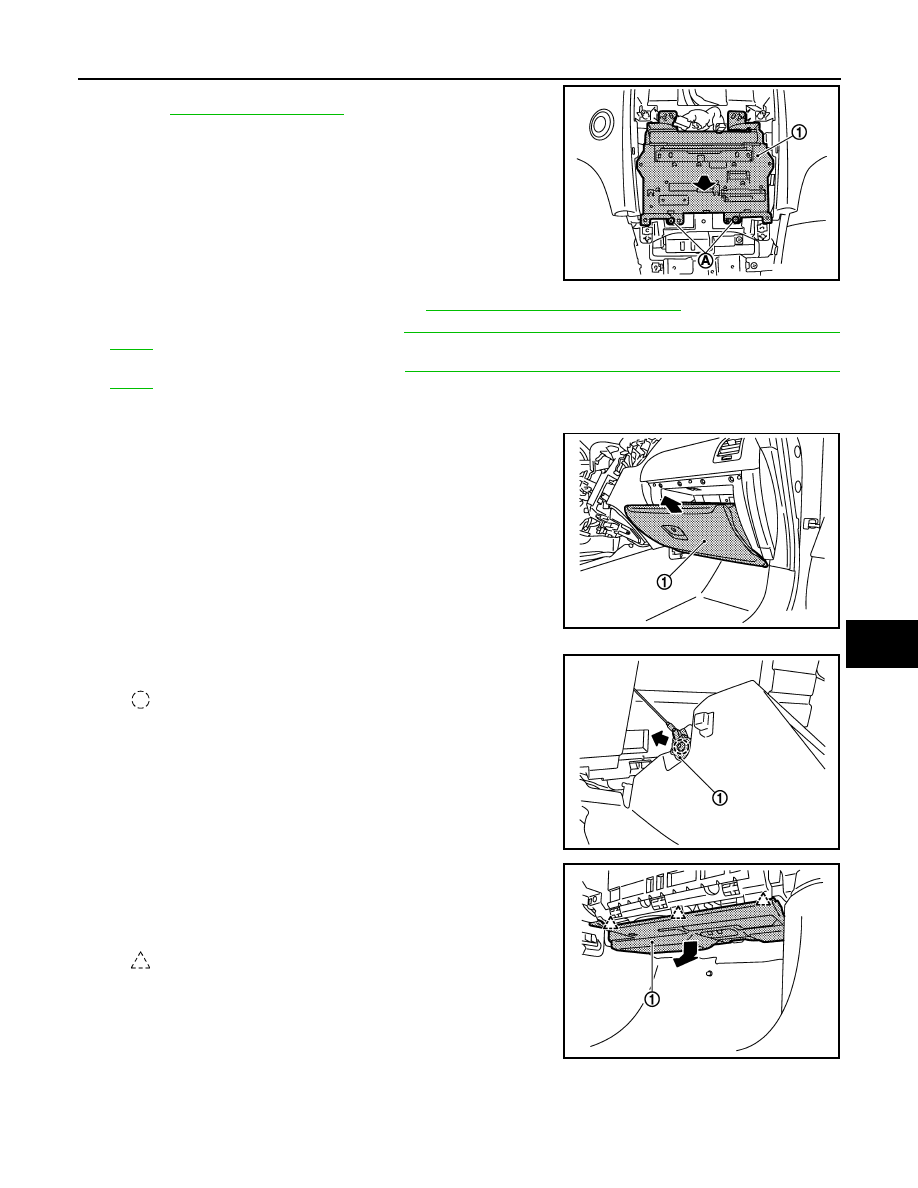
39. Remove AV control unit.
• Remove AV control unit (1) fixing screws (A).
• Pull back AV control unit.
• Disconnect harness connectors.
40. Remove push button ignition switch. Refer to
SEC-220, "Removal and Installation"
.
41. Remove front defroster grille LH. Refer to
VTL-13, "FRONT DEFROSTER GRILLE : Removal and Instal-
.
42. Remove front defroster grille RH. Refer to
VTL-13, "FRONT DEFROSTER GRILLE : Removal and Instal-
.
43. Remove glove box assembly.
• Open the glove box.
• Pull back glove box assembly (1).
• Remove damper pin (1) of left side.
44. Remove instrument lower cover RH.
• Pull downward, disengage pawls.
• Pull back instrument lower cover RH (1).
• Disconnect illumination lamp harness connector.
JMJIA1628ZZ
JMJIA1993ZZ
: Clip
JMJIA1994ZZ
: Pawl
JMJIA1995ZZ
Нет комментариевНе стесняйтесь поделиться с нами вашим ценным мнением.
Текст