Infiniti FX35, FX50 (S51). Manual — part 184
AV
B2707 SENSOR HARNESS OPEN [CR-RR]
AV-509
< DTC/CIRCUIT DIAGNOSIS >
[NAVIGATION (TWIN MONITOR)]
C
D
E
F
G
H
I
J
K
L
M
B
A
O
P
B2707 SENSOR HARNESS OPEN [CR-RR]
DTC Logic
INFOID:0000000005474863
DTC DETECTION LOGIC
Diagnosis Procedure
INFOID:0000000005474864
1.
CHECK HARNESS CORNER SENSOR (RR) SIGNAL CIRCUIT
1.
Turn ignition switch OFF.
2.
Disconnect sonar control unit connector and corner sensor (RR) connector.
3.
Check continuity between sonar control unit harness connector and corner sensor (RR) harness connec-
tor.
4.
Check continuity between sonar control unit harness connector and ground.
Is the inspection result normal?
YES
>> GO TO 2.
NO
>> Repair harness or connector.
2.
CHECK HARNESS CORNER SENSOR (RR) GROUND CIRCUIT
Check continuity between sonar control unit harness connector and corner sensor (RR) harness connector.
Is the inspection result normal?
YES
>> INSPECTION END
NO
>> Repair harness or connector.
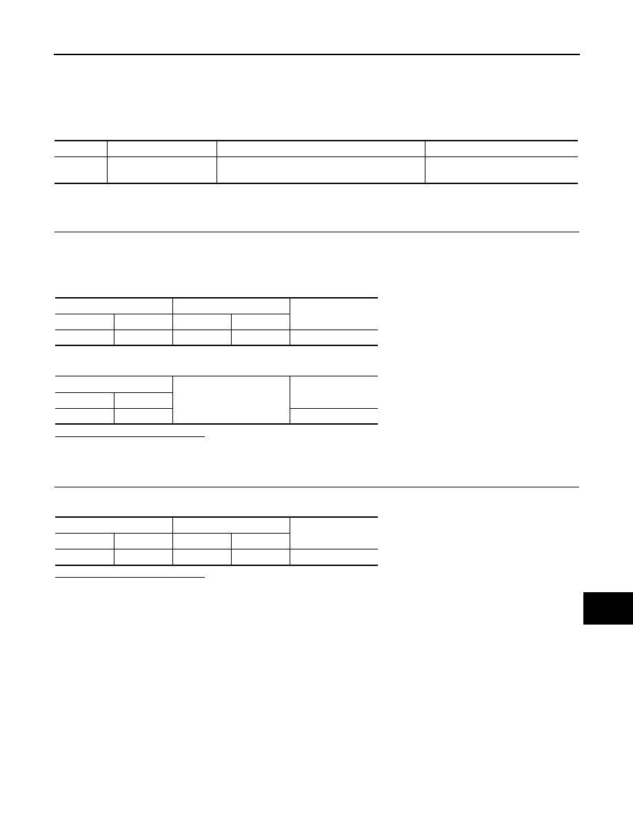
DTC No.
CONSULT-III indication
DTC detection condition
Troubleshooting
B2707
SENSOR HARNESS
OPEN [CR-RR] [B2707]
Corner sensor (RR) harness circuit is open.
Check corner sensor (RR) circuit.
Sonar control unit
Corner sensor (RR)
Continuity
Connector
Terminal
Connector
Terminal
M47
6
B256
1
Existed
Sonar control unit
Ground
Continuity
Connector
Terminal
M47
6
Not existed
Sonar control unit
Corner sensor (RR)
Continuity
Connector
Terminal
Connector
Terminal
M47
12
B256
2
Existed

AV-510
< DTC/CIRCUIT DIAGNOSIS >
[NAVIGATION (TWIN MONITOR)]
POWER SUPPLY AND GROUND CIRCUIT
POWER SUPPLY AND GROUND CIRCUIT
AV CONTROL UNIT
AV CONTROL UNIT : Diagnosis Procedure
INFOID:0000000005475121
1.
CHECK FUSE
Check for blown fuses.
Is the inspection result normal?
YES
>> GO TO 2.
NO
>> Be sure to eliminate cause of malfunction before installing new fuse.
2.
CHECK POWER SUPPLY CIRCUIT
Check voltage between AV control unit harness connectors and ground.
Is the inspection result normal?
YES
>> GO TO 3.
NO
>> Check harness between AV control unit and fuse.
3.
CHECK GROUND CIRCUIT
1.
Turn ignition switch OFF.
2.
Disconnect AV control unit connectors.
3.
Check continuity between AV control unit harness connectors and ground.
Is the inspection result normal?
YES
>> INSPECTION END
NO
>> Repair harness or connector.
FRONT DISPLAY UNIT
FRONT DISPLAY UNIT : Diagnosis Procedure
INFOID:0000000005475122
1.
CHECK FUSE
Check for blown fuses.
Is the inspection result normal?
YES
>> GO TO 2.
NO
>> Be sure to eliminate cause of malfunction before installing new fuse.
2.
CHECK POWER SUPPLY CIRCUIT
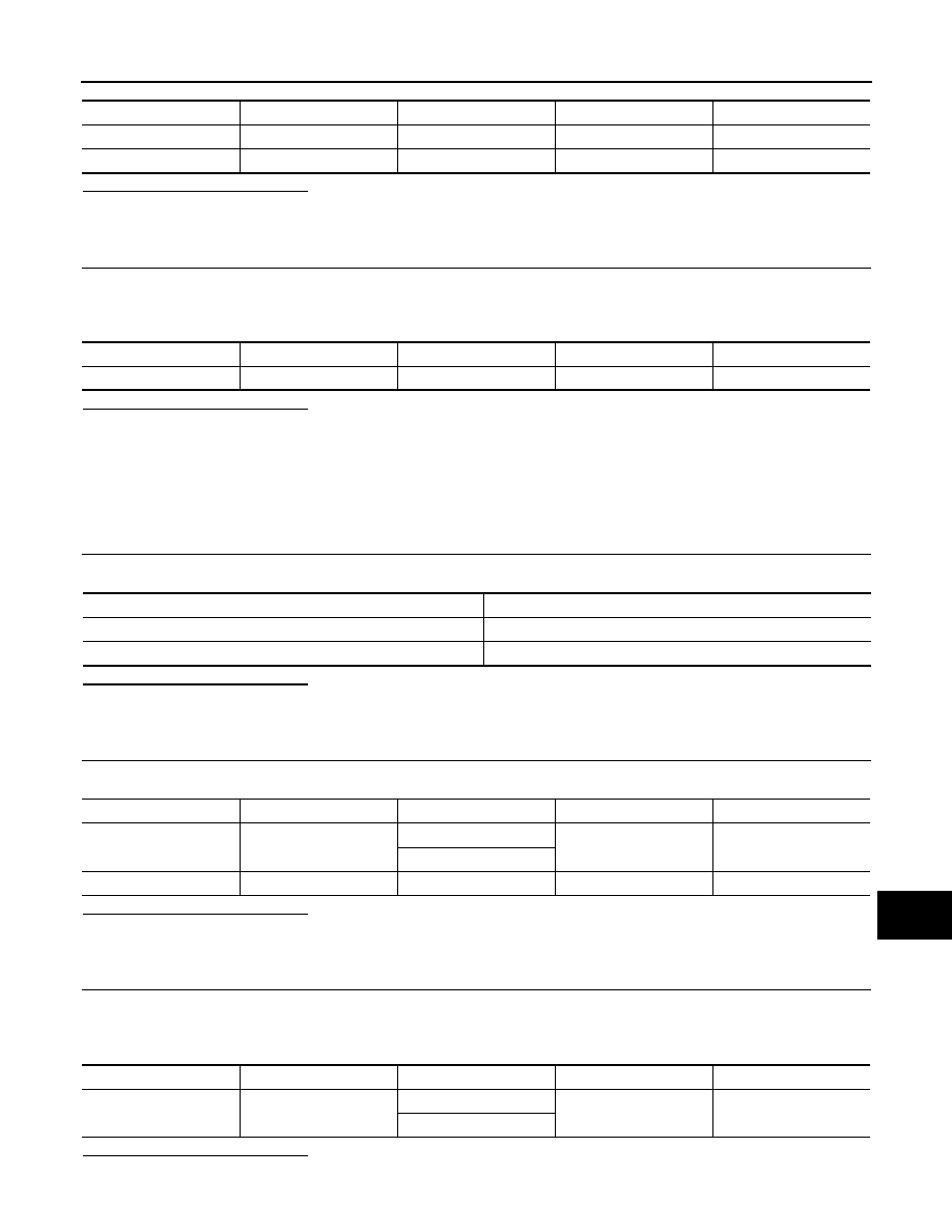
Check voltage between display unit harness connector and ground.
Power source
Fuse No.
Battery
34
Ignition switch ACC or ON
19
Signal name
Connector No.
Terminal No.
Ignition switch position
Value (Approx.)
Battery power supply
M208
19
OFF
Battery voltage
ACC power supply
M208
7
ACC
Battery voltage
Signal name
Connector No.
Terminal No.
Ignition switch position
Continuity
Ground
M208
20
OFF
Existed
Power source
Fuse No.
Battery
34
Ignition switch ACC or ON
19
AV
POWER SUPPLY AND GROUND CIRCUIT
AV-511
< DTC/CIRCUIT DIAGNOSIS >
[NAVIGATION (TWIN MONITOR)]
C
D
E
F
G
H
I
J
K
L
M
B
A
O
P
Is the inspection result normal?
YES
>> GO TO 3.
NO
>> Check harness between display unit and fuse.
3.
CHECK GROUND CIRCUIT
1.
Turn ignition switch OFF.
2.
Disconnect display unit connector.
3.
Check continuity between display unit harness connector and ground.
Is the inspection result normal?
YES
>> INSPECTION END
NO
>> Repair harness or connector.
REAR DISPLAY UNIT
REAR DISPLAY UNIT : Diagnosis Procedure
INFOID:0000000005475113
1.
CHECK FUSE
Check for blown fuses.
Is the inspection result normal?
YES
>> GO TO 2.
NO
>> Be sure to eliminate cause of malfunction before installing new fuse.
2.
CHECK POWER SUPPLY CIRCUIT
Check voltage between rear display unit harness connector and ground.
Is the inspection result normal?
YES
>> GO TO 3.
NO
>> Check harness between rear display unit and fuse.
3.
CHECK GROUND CIRCUIT
1.
Turn ignition switch OFF.
2.
Disconnect rear display unit connector.
3.
Check continuity between rear display unit harness connector and ground.
Is the inspection result normal?
YES
>> INSPECTION END
Signal name
Connector No.
Terminal No.
Ignition switch position
Value (Approx.)
Battery power supply
M195
11
OFF
Battery voltage
ACC power supply
M195
23
ACC
Battery voltage
Signal name
Connector No.
Terminal No.
Ignition switch position
Continuity
Ground
M195
12
OFF
Existed
Power source
Fuse No.
Battery
34
Ignition switch ACC or ON
19
Signal name
Connector No.
Terminal No.
Ignition switch position
Value (Approx.)
Battery power supply
B26
3
OFF
Battery voltage
4
ACC power supply
B26
6
ACC
Battery voltage
Signal name
Connector No.
Terminal No.
Ignition switch position
Continuity
Ground
B26
1
OFF
Existed
2

AV-512
< DTC/CIRCUIT DIAGNOSIS >
[NAVIGATION (TWIN MONITOR)]
POWER SUPPLY AND GROUND CIRCUIT
NO
>> Repair harness or connector.
VIDEO DISTRIBUTOR
VIDEO DISTRIBUTOR : Diagnosis Procedure
INFOID:0000000005475114
1.
CHECK FUSE
Check for blown fuses.
Is the inspection result normal?
YES
>> GO TO 2.
NO
>> Be sure to eliminate cause of malfunction before installing new fuse.
2.
CHECK POWER SUPPLY CIRCUIT
Check voltage between video distributor harness connector and ground.
Is the inspection result normal?
YES
>> GO TO 3.
NO
>> Check harness between video distributor and fuse.
3.
CHECK GROUND CIRCUIT
1.
Turn ignition switch OFF.
2.
Disconnect video distributor connector.
3.
Check continuity between video distributor harness connector and ground.
Is the inspection result normal?
YES
>> INSPECTION END
NO
>> Repair harness or connector.
BOSE AMP.
BOSE AMP. : Diagnosis Procedure
INFOID:0000000005475124
1.
CHECK FUSE
Check for blown fuses.
Is the inspection result normal?
YES
>> GO TO 2.
NO
>> Be sure to eliminate cause of malfunction before installing new fuse.
2.
CHECK POWER SUPPLY CIRCUIT
Check voltage between BOSE amp. harness connector and ground.
Power source
Fuse No.
Battery
34
Ignition switch ACC or ON
19
Signal name
Connector No.
Terminal No.
Ignition switch position
Value (Approx.)
Battery power supply
M99
54
OFF
Battery voltage
ACC power supply
M99
55
ACC
Battery voltage
Signal name
Connector No.
Terminal No.
Ignition switch position
Continuity
Ground
M99
53
OFF
Existed
Power source
Fuse No.
Battery
8
Signal name
Connector No.
Terminal No.
Ignition switch position
Value (Approx.)
Battery power supply
B42
11
OFF
Battery voltage
Нет комментариевНе стесняйтесь поделиться с нами вашим ценным мнением.
Текст