Infiniti FX35, FX50 (S51). Manual — part 185
AV
POWER SUPPLY AND GROUND CIRCUIT
AV-513
< DTC/CIRCUIT DIAGNOSIS >
[NAVIGATION (TWIN MONITOR)]
C
D
E
F
G
H
I
J
K
L
M
B
A
O
P
Is the inspection result normal?
YES
>> GO TO 3.
NO
>> Check harness between BOSE amp. and fuse.
3.
CHECK GROUND CIRCUIT
1.
Turn ignition switch OFF.
2.
Disconnect BOSE amp. connector.
3.
Check continuity between BOSE amp. harness connector and ground.
Is the inspection result normal?
YES
>> INSPECTION END
NO
>> Repair harness or connector.
AROUND VIEW MONITOR CONTROL UNIT
AROUND VIEW MONITOR CONTROL UNIT : Diagnosis Procedure
INFOID:0000000005475125
1.
CHECK FUSE
Check for blown fuses.
Is inspection result normal?
YES
>> GO TO 2.
NO
>> Be sure to eliminate cause of malfunction before installing new fuse.
2.
CHECK POWER SUPPLY CIRCUITS
Check voltage between around view monitor control unit harness connector and ground.
Is inspection result normal?
YES
>> GO TO 3.
NO
>> Check harness between around view monitor control unit and fuse.
3.
CHECK GROUND CIRCUIT
1.
Turn ignition switch OFF.
2.
Disconnect around view monitor control unit connector.
3.
Check continuity between around view monitor control unit harness connector and ground.
Is inspection result normal?
YES
>> INSPECTION END
NO
>> Repair harness or connector.
SONAR CONTROL UNIT (WITH AROUND VIEW MONITOR)
SONAR CONTROL UNIT (WITH AROUND VIEW MONITOR) : Diagnosis Procedure
INFOID:0000000005475126
1.
CHECK FUSE
Signal name
Connector No.
Terminal No.
Ignition switch position
Continuity
Ground
B42
12
OFF
Existed
Power source
Fuse No.
Battery
34
Ignition switch ACC
19
Signal name
Connector No.
Terminal No.
Ignition switch position
Value (Approx.)
Battery power supply
B46
2
OFF
Battery voltage
ACC power supply
B46
4
ACC
Battery voltage
Signal name
Connector No.
Terminal No.
Ignition switch position
Continuity
Ground
B46
1
OFF
Existed

AV-514
< DTC/CIRCUIT DIAGNOSIS >
[NAVIGATION (TWIN MONITOR)]
POWER SUPPLY AND GROUND CIRCUIT
Check for blown fuses.
Is the inspection result normal?
YES
>> GO TO 2.
NO
>> Be sure to eliminate cause of malfunction before installing new fuse.
2.
CHECK POWER SUPPLY CIRCUIT
1.
Turn ignition switch ON.
2.
Check voltage between sonar control unit harness connector and ground.
Is the inspection result normal?
YES
>> GO TO 3.
NO
>> Repair or replace sonar control unit power supply harness.
3.
CHECK GROUND CIRCUIT
1.
Turn ignition switch OFF.
2.
Disconnect sonar control unit connector.
3.
Check continuity between sonar control unit harness connector and ground.
Is the inspection result normal?
YES
>> INSPECTION END
NO
>> Repair or replace sonar control unit ground harness.
Power source
Fuse No.
Ignition switch ACC or ON
19
Signal name
Connector No.
Terminal No.
Ignition switch position
Value (Approx.)
Battery power supply
M47
13
ACC
Battery voltage
Signal name
Connector No.
Terminal No.
Ignition switch position
Continuity
Ground
M47
24
OFF
Existed
AV
RGB (G: GREEN) SIGNAL CIRCUIT (VIDEO DISTRIBUTOR TO REAR DISPLAY
UNIT)
AV-515
< DTC/CIRCUIT DIAGNOSIS >
[NAVIGATION (TWIN MONITOR)]
C
D
E
F
G
H
I
J
K
L
M
B
A
O
P
RGB (G: GREEN) SIGNAL CIRCUIT (VIDEO DISTRIBUTOR TO REAR DIS-
PLAY UNIT)
Description
INFOID:0000000005247316
Transmit the image displayed with video distributor with RGB signal to the rear display unit.
Diagnosis Procedure
INFOID:0000000005247317
1.
CHECK CONTINUITY RGB (G: GREEN) SIGNAL CIRCUIT
1.
Turn ignition switch OFF.
2.
Disconnect rear display unit connector and video distributor connector.
3.
Check continuity between rear display unit harness connector and video distributor harness connector.
4.
Check continuity between rear display unit harness connector and ground.
Is the inspection result normal?
YES
>> GO TO 2.
NO
>> Repair harness or connector.
2.
CHECK RGB (G: GREEN) SIGNAL
1.
Connect rear display unit connector and video distributor connector.
2.
Turn ignition switch ON.
3.
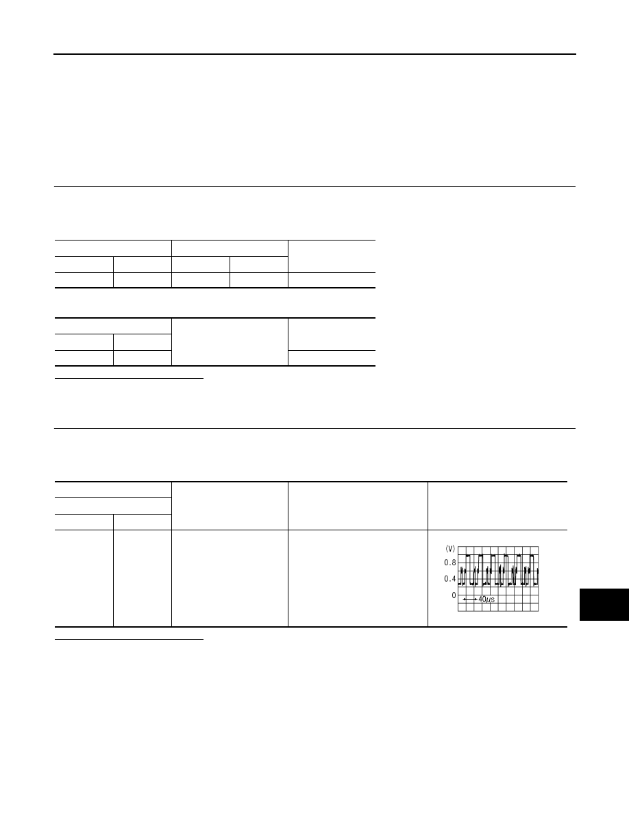
Check signal between rear display unit harness connector and ground using an oscilloscope.
Is the inspection result normal?
YES
>> Replace rear display unit.
NO
>> Replace video distributor.
Rear display unit
Video distributor
Continuity
Connector
Terminal
Connector
Terminal
B26
21
M97
26
Existed
Rear display unit
Ground
Continuity
Connector
Terminal
B26
21
Not existed
(+)
(
−
)
Condition
Reference value
Rear display unit
Connector
Terminal
B26
21
Ground
Rear seat remote controller opera-
tion when AUX or DVD image is
displayed on rear display unit.
JSNIA1030ZZ
AV-516
< DTC/CIRCUIT DIAGNOSIS >
[NAVIGATION (TWIN MONITOR)]
RGB (R: RED) SIGNAL CIRCUIT (VIDEO DISTRIBUTOR TO REAR DISPLAY
UNIT)
RGB (R: RED) SIGNAL CIRCUIT (VIDEO DISTRIBUTOR TO REAR DIS-
PLAY UNIT)
Description
INFOID:0000000005247314
Transmit the image displayed with video distributor with RGB signal to the rear display unit.
Diagnosis Procedure
INFOID:0000000005247315
1.
CHECK CONTINUITY RGB (R: RED) SIGNAL CIRCUIT
1.
Turn ignition switch OFF.
2.
Disconnect rear display unit connector and video distributor connector.
3.
Check continuity between rear display unit harness connector and video distributor harness connector.
4.
Check continuity between rear display unit harness connector and ground.
Is the inspection result normal?
YES
>> GO TO 2.
NO
>> Repair harness or connector.
2.
CHECK RGB (R: RED) SIGNAL
1.
Connect rear display unit connector and video distributor connector.
2.
Turn ignition switch ON.
3.
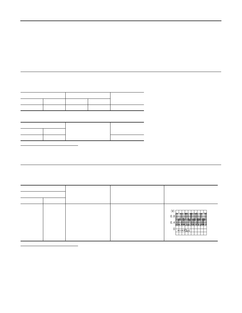
Check signal between rear display unit harness connector and ground using an oscilloscope.
Is the inspection result normal?
YES
>> Replace rear display unit.
NO
>> Replace video distributor.
Rear display unit
Video distributor
Continuity
Connector
Terminal
Connector
Terminal
B26
22
M97
25
Existed
Rear display unit
Ground
Continuity
Connector
Terminal
B26
22
Not existed
(+)
(
−
)
Condition
Reference value
Rear display unit
Connector
Terminal
B26
22
Ground
Rear seat remote controller opera-
tion when AUX or DVD image is
displayed on rear display unit.
JSNIA1029ZZ
Нет комментариевНе стесняйтесь поделиться с нами вашим ценным мнением.
Текст