Infiniti FX35, FX50 (S51). Manual — part 1946
FRONT WIPER AND WASHER SYSTEM
WW-7
< SYSTEM DESCRIPTION >
C
D
E
F
G
H
I
J
K
M
A
B
WW
N
O
P
• BCM stops the transmitting of the front wiper request signal when the ignition switch is OFF.
• IPDM E/R turns the front wiper relay OFF when the ignition switch is OFF.
FRONT WIPER OPERATION LINKED WITH WASHER
• BCM transmits the front wiper request signal (LO) to IPDM E/R with CAN communication according to the
washer linked operating condition of the front wiper.
• BCM transmits the front wiper request signal (LO) so that the front wiper operates approximately 2 times
when the front washer switch OFF is detected.
Washer linked operating condition of front wiper
- Ignition switch ON
- Front washer switch ON (0.4 second or more)
• IPDM E/R turns ON the integrated front wiper relay according to the front wiper request signal (LO).
• The washer pump is grounded through the combination switch with the front washer switch ON.
FAIL-SAFE FUNCTION
Front Wiper control
IPDM E/R performs the fail-safe function when the front wiper auto stop circuit is malfunctioning. Refer to
.
Rain Sensor Malfunction
• BCM judges the rain sensor serial link error by the rain sensor serial link condition and detects the rain sen-
sor malfunction by rain sensor malfunction signal.
• When BCM detects the rain sensor serial link error or the rain sensor malfunction while front wiper AUTO
operation, BCM operates a fail-safe control.
NOTE:
If rain sensor malfunction is detected when ignition switch is turned OFF
⇒
ON and front wiper switch is INT
position, BCM operates front wiper LO.
WW-8
< SYSTEM DESCRIPTION >
FRONT WIPER AND WASHER SYSTEM
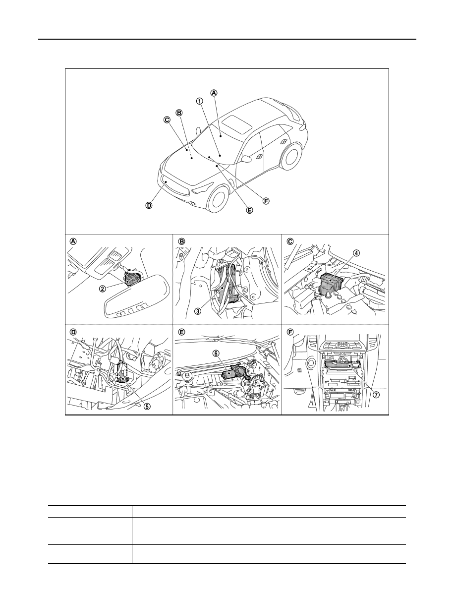
WITH RAIN SENSOR : Component Parts Location
INFOID:0000000005234736
WITH RAIN SENSOR : Component Description
INFOID:0000000005234737
1.
Combination switch
2.
Rain sensor
3.
BCM
4.
IPDM E/R
5.
Washer pump
6.
Front wiper motor
7.
Unified meter and A/C amp.
A.
Wind shield upper
B.
Dash side lower (Passenger side)
C.
Engine room (right side)
D.
Radiator core support (RH)
E.
Cowl top, left side of engine room
F.
Behind cluster lid C
JPLIA1242ZZ
Part
Description
BCM
• Judges each switch status by the combination switch reading function.
• Requests (with CAN communication) the front wiper relay and the front wiper high relay ON to
IPDM E/R.
IPDM E/R
• Controls the integrated relay according to the request (with CAN communication) from BCM.
• Performs the auto stop control of the front wiper.
FRONT WIPER AND WASHER SYSTEM
WW-9
< SYSTEM DESCRIPTION >
C
D
E
F
G
H
I
J
K
M
A
B
WW
N
O
P
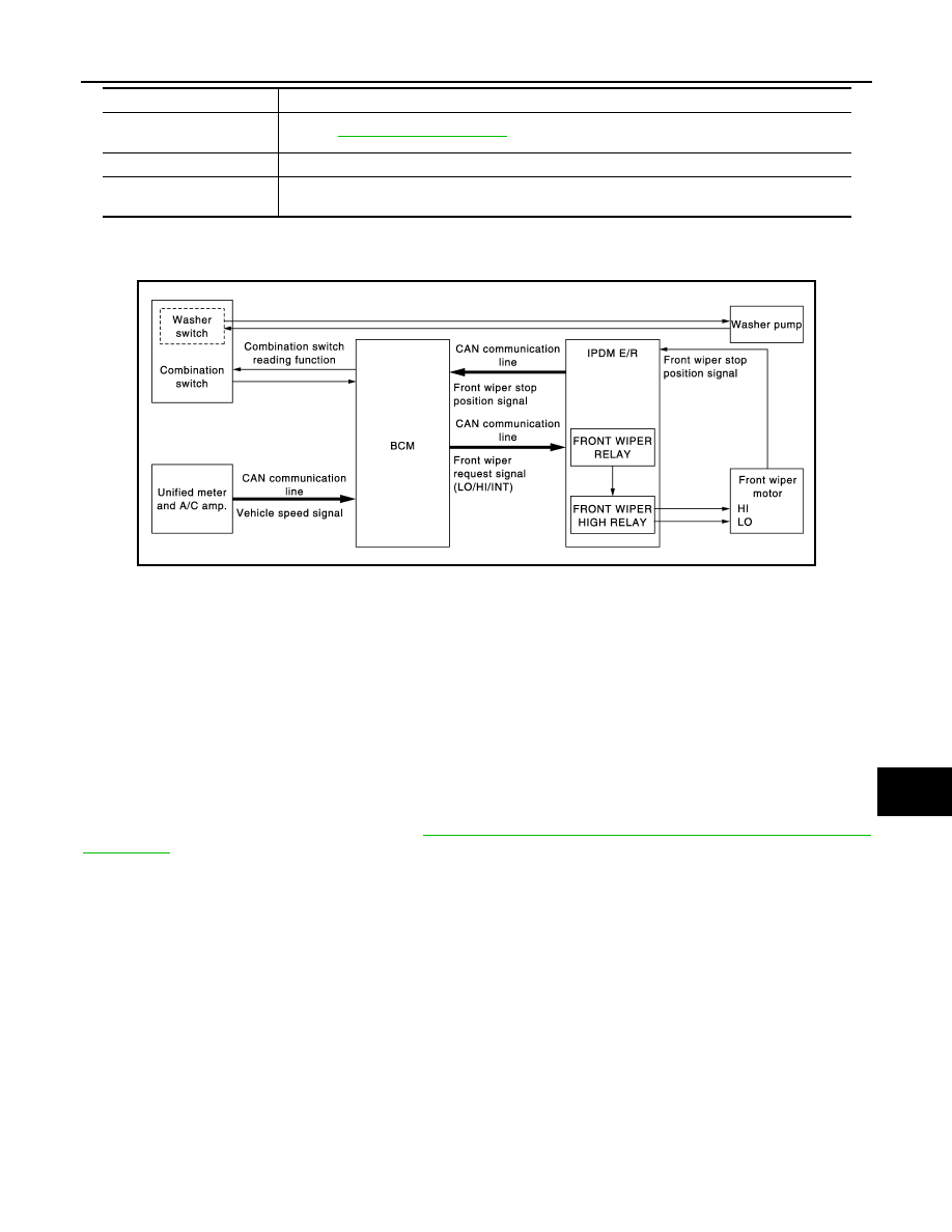
WITHOUT RAIN SENSOR
WITHOUT RAIN SENSOR : System Diagram
INFOID:0000000005234738
WITHOUT RAIN SENSOR : System Description
INFOID:0000000005234739
OUTLINE
The front wiper is controlled by each function of BCM and IPDM E/R.
Control by BCM
• Combination switch reading function
• Front wiper control function
Control by IPDM E/R
• Front wiper control function
• Relay control function
Combination meter indicates low washer fluid warning judged with the signal from the washer level switch. For
details of low washer fluid warning, refer to
MWI-25, "WARNING LAMPS/INDICATOR LAMPS : System
.
FRONT WIPER BASIC OPERATION
• BCM detects the combination switch condition by the combination switch reading function.
• BCM transmits the front wiper request signal to IPDM E/R with CAN communication depending on each
operating condition of the front wiper.
• IPDM E/R turns ON/OFF the integrated front wiper relay and the front wiper high relay according to the front
wiper request signal. IPDM E/R provides the power supply to operate the front wiper HI/LO operation.
FRONT WIPER LO OPERATION
• BCM transmits the front wiper request signal (LO) to IPDM E/R with CAN communication according to the
front wiper LO operating condition.
Front wiper LO operating condition
- Ignition switch ON
- Front wiper switch LO or front wiper switch MIST (while pressing)
• IPDM E/R turns ON the integrated front wiper relay according to the front wiper request signal (LO).
FRONT WIPER HI OPERATION
Combination switch
(Wiper & washer switch)
Refer to
Unified meter and A/C amp.
Transmits the vehicle speed signal to BCM with CAN communication.
Rain sensor
Detects water droplets on the windshield with infrared rays, and transmits the rain sensor signal
to BCM through the rain sensor serial link.
Part
Description
JPLIA1255GB
WW-10
< SYSTEM DESCRIPTION >
FRONT WIPER AND WASHER SYSTEM
• BCM transmits the front wiper request signal (HI) to IPDM E/R with CAN communication according to the
front wiper HI operating condition.
Front wiper HI operating condition
- Ignition switch ON
- Front wiper switch HI
• IPDM E/R turns ON the integrated front wiper relay and the front wiper high relay according to the front wiper
request signal (HI).
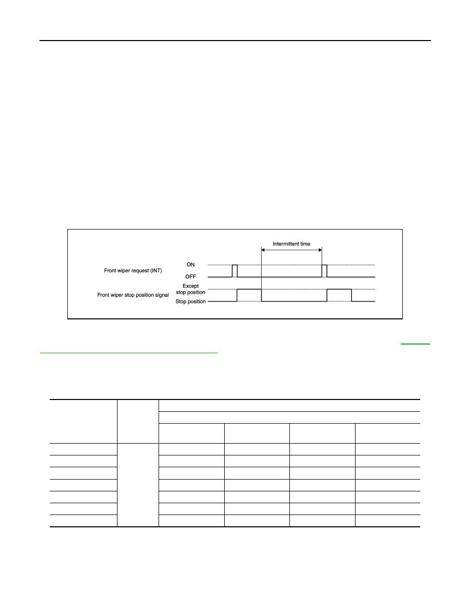
FRONT WIPER INT OPERATION
• BCM transmits the front wiper request signal (INT) to IPDM E/R with CAN communication depending on the
front wiper INT operating condition and intermittent operation delay interval according to the wiper intermit-
tent dial position.
Front wiper INT operating condition
- Ignition switch ON
- Front wiper switch INT
• IPDM E/R turns ON the integrated front wiper relay so that the front wiper is operated only once according to
the front wiper request signal (INT).
• BCM detects stop position/except stop position of the front wiper motor according to the front wiper stop
position signal received from IPDM E/R with CAN communication.
• BCM transmits the front wiper request signal (INT) again after the intermittent operation delay interval.
NOTE:
Factory setting of the front wiper intermittent operation is the operation without vehicle speed. Front wiper
intermittent operation can be set to the operation with vehicle speed by CONSULT-III. Refer to
"WIPER : CONSULT-III Function (BCM - WIPER)"
Front wiper intermittent operation with vehicle speed
• BCM calculates the intermittent operation delay interval from the following
- Vehicle speed signal (received from the unified meter and A/C amp. with CAN communication)
- Wiper intermittent dial position
Unit: Second
*: When without vehicle speed setting
FRONT WIPER AUTO STOP OPERATION
• BCM stops transmitting the front wiper request signal when the front wiper switch is turned OFF.
• IPDM E/R detects the front wiper stop position signal from the front wiper motor and detects the front wiper
motor position (stop position/except stop position).
Wiper intermittent
dial position
Intermittent
operation
interval
Intermittent operation delay Interval
Vehicle speed
0 – 5 km/h
(0 – 3.1 MPH)
5 – 35 km/h
(3.1 – 21.7 MPH)
35 – 65 km/h
(21.7 – 40.4 MPH)*
65 km/h (40.4MPH)
or more
1
Short
↑
↓
Long
0.8
0.6
0.4
0.24
2
4
3
2
1.2
3
10
7.5
5
3
4
16
12
8
4.8
5
24
18
12
7.2
6
32
24
16
9.6
7
42
31.5
21
12.6
JPLIA1256GB
Нет комментариевНе стесняйтесь поделиться с нами вашим ценным мнением.
Текст