Infiniti FX35, FX50 (S51). Manual — part 1945
DIAGNOSIS AND REPAIR WORKFLOW
WW-3
< BASIC INSPECTION >
C
D
E
F
G
H
I
J
K
M
A
B
WW
N
O
P
BASIC INSPECTION
DIAGNOSIS AND REPAIR WORKFLOW
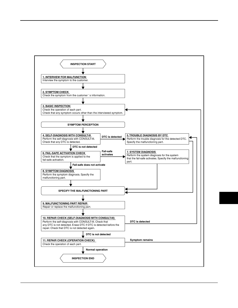
Work Flow
INFOID:0000000005234733
OVERALL SEQUENCE
DETAILED FLOW
1.
INTERVIEW FOR MALFUNCTION
Interview the symptom to the customer.
JPLIA0313GB

WW-4
< BASIC INSPECTION >
DIAGNOSIS AND REPAIR WORKFLOW
>> GO TO 2.
2.
SYMPTOM CHECK
Check the symptom from the customer's information.
>> GO TO 3.
3.
BASIC INSPECTION
Check the operation of each part. Check that any symptom occurs other than the interviewed symptom.
>> GO TO 4.
4.
SELF-DIAGNOSIS WITH CONSULT-III
Perform the self-diagnosis with CONSULT-III. Check that any DTC is detected.
Is any DTC detected?
YES
>> GO TO 5.
NO
>> GO TO 6.
5.
TROUBLE DIAGNOSIS BY DTC
Perform the trouble diagnosis for the detected DTC. Specify the malfunctioning part.
>> GO TO 9.
6.
FAIL-SAFE ACTIVATION CHECK
Check that the symptom is applied to the fail-safe activation.
Does the fail-safe activate?
YES
>> GO TO 7.
NO
>> GO TO 8.
7.
SYSTEM DIAGNOSIS
Perform the system diagnosis for the system that the fail-safe activates. Specify the malfunctioning part.
>> GO TO 9.
8.
SYMPTOM DIAGNOSIS
Perform the symptom diagnosis. Specify the malfunctioning part.
>> GO TO 9.
9.
MALFUNCTION PART REPAIR
Repair or replace the malfunctioning part.
>> GO TO 10.
10.
REPAIR CHECK (SELF-DIAGNOSIS WITH CONSULT-III)
Perform the self-diagnosis with CONSULT-III. Check that any DTC is not detected. Erase DTC if DTC is
detected before the repair. Check that DTC is not detected again.
Is any DTC detected?
YES
>> GO TO 5.
NO
>> GO TO 11.
11.
REPAIR CHECK (OPERATION CHECK)
Check the operation of each part.
Does it operate normally?
YES
>> INSPECTION END
NO
>> GO TO 3.

FRONT WIPER AND WASHER SYSTEM
WW-5
< SYSTEM DESCRIPTION >
C
D
E
F
G
H
I
J
K
M
A
B
WW
N
O
P
SYSTEM DESCRIPTION
FRONT WIPER AND WASHER SYSTEM
WITH RAIN SENSOR
WITH RAIN SENSOR : System Diagram
INFOID:0000000005234734
WITH RAIN SENSOR : System Description
INFOID:0000000005234735
OUTLINE
The front wiper is controlled by each function of BCM and IPDM E/R.
Control by BCM
• Combination switch reading function
• Front wiper control function
Control by IPDM E/R
• Front wiper control function
• Relay control function
Combination meter indicates low washer fluid warning judged with the signal from the washer level switch. For
details of low washer fluid warning, refer to
MWI-25, "WARNING LAMPS/INDICATOR LAMPS : System
.
FRONT WIPER BASIC OPERATION
• BCM detects the combination switch condition by the combination switch reading function.
• BCM transmits the front wiper request signal to IPDM E/R with CAN communication depending on each
operating condition of the front wiper.
• IPDM E/R turns ON/OFF the integrated front wiper relay and the front wiper high relay according to the front
wiper request signal. IPDM E/R provides the power supply to operate the front wiper HI/LO operation.
FRONT WIPER LO OPERATION
• BCM transmits the front wiper request signal (LO) to IPDM E/R with CAN communication according to the
front wiper LO operating condition.
Front wiper LO operating condition
- Ignition switch ON
- Front wiper switch LO or front wiper switch MIST (while pressing)
• IPDM E/R turns ON the integrated front wiper relay according to the front wiper request signal (LO).
FRONT WIPER HI OPERATION
• BCM transmits the front wiper request signal (HI) to IPDM E/R with CAN communication according to the
front wiper HI operating condition.
Front wiper HI operating condition
- Ignition switch ON
- Front wiper switch HI
JPLIA1254GB
WW-6
< SYSTEM DESCRIPTION >
FRONT WIPER AND WASHER SYSTEM
• IPDM E/R turns ON the integrated front wiper relay and the front wiper high relay according to the front wiper
request signal (HI).
FRONT WIPER AUTO OPERATION
Rain Sensing
Rain level and sensor conditions are detected by rain sensor.
• BCM transmits the vehicle conditions (vehicle speed, front wiper condition, rain sensor sensitivity setting,
etc.) to the rain sensor via the rain sensor serial link.
• Rain sensor judges a wiping speed for front wiper by rain condition and the vehicle conditions. And it trans-
mits the wiping speed request signal to the BCM via the rain sensor serial link.
Auto Wiping Operation
• BCM receives the wiping speed request signal from the rain sensor via the rain sensor serial link.
• BCM controls front wiper operation according to the wiping speed request signals. And it transmits the front
wiper request signals (LO or HI) to the IPDM E/R via CAN communication line.
Front wiper AUTO operating condition
- Ignition switch ON
- Front wiper switch INT
NOTE:
When the front wiper switch is turned to INT position, front wiper operates once regardless of a rainy condition.
Rain Sensor Sensitivity Setting
BCM determines rain sensor sensitivity according to a wiper volume.
NOTE:
When the wiper volume is turned up at 1 level with front wiper AUTO operating condition, front wiper operates
once.
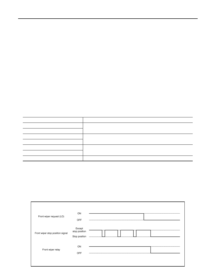
FRONT WIPER AUTO STOP OPERATION
• BCM stops transmitting the front wiper request signal when the front wiper switch is turned OFF.
• IPDM E/R detects the front wiper stop position signal from the front wiper motor and detects the front wiper
motor position (stop position/except stop position).
• When the front wiper request signal is stopped, IPDM E/R turns ON the front wiper relay until the front wiper
motor returns to the stop position.
NOTE:
Wiper intermittent dial position
Sensitivity
1
High sensitivity
2
3
Medium
−
high sensitivity
4
5
Low
−
medium sensitivity
6
7
Low sensitivity
JPLIA0410GB
Нет комментариевНе стесняйтесь поделиться с нами вашим ценным мнением.
Текст