Infiniti FX35, FX50 (S51). Manual — part 157
AV
DIAGNOSIS SYSTEM (SONAR CONTROL UNIT)
AV-401
< SYSTEM DESCRIPTION >
[NAVIGATION (TWIN MONITOR)]
C
D
E
F
G
H
I
J
K
L
M
B
A
O
P
The default of this model is “FAR”.

AV-402
< ECU DIAGNOSIS INFORMATION >
[NAVIGATION (TWIN MONITOR)]
AV CONTROL UNIT
ECU DIAGNOSIS INFORMATION
AV CONTROL UNIT
Reference Value
INFOID:0000000005474741
VALUES ON THE DIAGNOSIS TOOL
CONSULT-III MONITOR ITEM
*: Check 10 seconds later, after closing all doors.
TERMINAL LAYOUT
PHYSICAL VALUES
Monitor Item
Condition
Value/Status
VHCL SPD SIG
Ignition switch
ON
Vehicle speed > 0 km/h (0 MPH)
On
Vehicle speed = 0 km/h (0 MPH)
Off
PKB SIG
Ignition switch
ON
Parking brake is applied.
On
Parking brake is released.
Off
ILLUM SIG
Ignition switch
ON
Light switch ON
On
Light switch OFF
Off
IGN SIG
Ignition switch
ON
—
On
Ignition switch
ACC
—
Off
REV SIG
Ignition switch
ON
Selector lever in R position
On
Selector lever in any position other than R
Off
SIDE VIEW SW
Ignition switch
ON
This item is displayed, but cannot be moni-
tored.
Off
ROOM LAMP
*
Ignition switch
ON
After opening any door; 5 seconds
On
Except for above.
Off
JSNIA2480ZZ
AV
AV CONTROL UNIT
AV-403
< ECU DIAGNOSIS INFORMATION >
[NAVIGATION (TWIN MONITOR)]
C
D
E
F
G
H
I
J
K
L
M
B
A
O
P
Terminal
(Wire color)
Description
Condition
Reference value
(Approx.)
+
–
Signal name
Input/
Output
1
(V)
Ground
AMP. ON signal
Input
Ignition
switch
ON
—
12.0 V
2
(P)
3
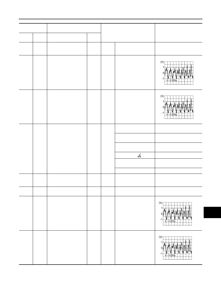
(L)
Sound signal front LH
Output
Ignition
switch
ON
Sound output
4
(V)
5
(LG)
Sound signal rear LH
Output
Ignition
switch
ON
Sound output
6
(P)
15
(B)
Steering switch signal A
Input
Ignition
switch
ON
Keep pressing SOURCE
switch.
0 V
Keep pressing MENU UP
switch.
1.0 V
Keep pressing MENU
DOWN switch.
2.0 V
Keep pressing
switch
3.0 V
Keep pressing ENTER
switch.
4.0 V
Except for above.
5.0 V
7
(V)
Ground
ACC power supply
Input
Ignition
switch
ACC
—
Battery voltage
10
(B)
—
Shield
—
—
—
—
11
(R)
12
(G)
Sound signal front RH
Output
Ignition
switch
ON
Sound output
13
(BR)
14
(Y)
Sound signal rear RH
Output
Ignition
switch
ON
Sound output
SKIB3609E
SKIB3609E
SKIB3609E
SKIB3609E
AV-404
< ECU DIAGNOSIS INFORMATION >
[NAVIGATION (TWIN MONITOR)]
AV CONTROL UNIT
16
(L)
15
(B)
Steering switch signal B
Input
Ignition
switch
ON
Keep pressing VOL DOWN
switch.
0 V
Keep pressing VOL UP
switch.
1.0 V
Keep pressing
switch.
2.0 V
Keep pressing
switch.
3.0 V
Except for above.
5.0 V
19
(Y)
Ground
Battery power supply
Input
Ignition
switch
OFF
—
Battery voltage
20
(B)
Ground
Ground
—
Ignition
switch
ON
—
0 V
26
(Y)
Ground
AUX image signal
Input
Ignition
switch
ON
At AUX image is displayed.
29
(SB)
Ground
Disk eject signal
Input
Ignition
switch
ON
Pressing the eject switch.
0 V
Except for above.
5.0 V
30
(SB)
Ground
Mode change signal
Output
Ignition
switch
ON
Driver's Audio Stage ON
0 V
Driver's Audio Stage OFF
8.5 V
33
(G)
Ground
Composite image ground
—
Ignition
switch
ON
—
0 V
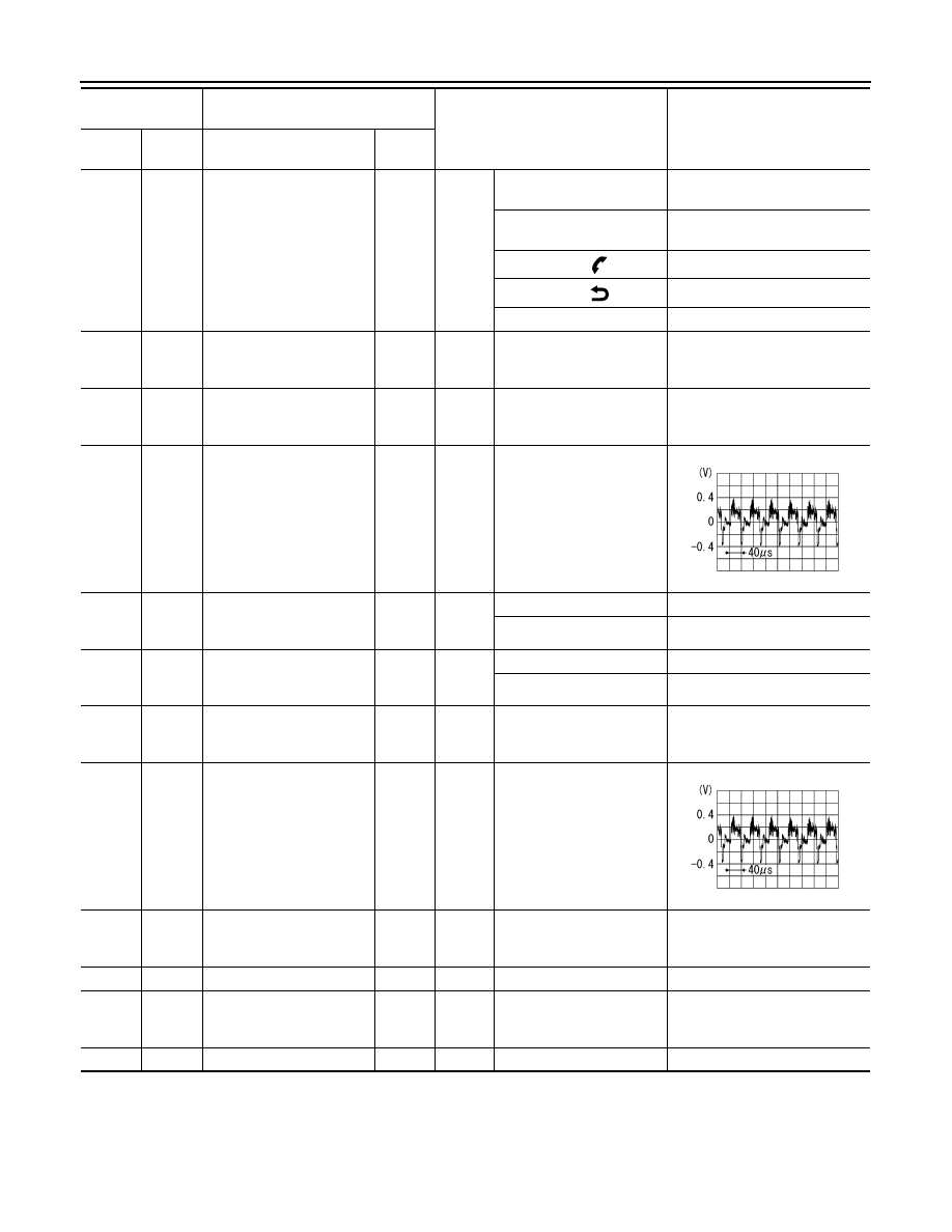
34
(R)
Ground
Composite image signal
Output
Ignition
switch
ON
At DVD image is displayed.
46
(BR)
Ground
AUX image signal ground
—
Ignition
switch
ON
—
0 V
47
—
Shield
—
—
—
—
49
(BR)
Ground
Switch ground
—
Ignition
switch
ON
—
0 V
53
—
Shield
—
—
—
—
Terminal
(Wire color)
Description
Condition
Reference value
(Approx.)
+
–
Signal name
Input/
Output
SKIB2251J
SKIB2251J
Нет комментариевНе стесняйтесь поделиться с нами вашим ценным мнением.
Текст