Infiniti FX35, FX50 (S51). Manual — part 158
AV
AV CONTROL UNIT
AV-405
< ECU DIAGNOSIS INFORMATION >
[NAVIGATION (TWIN MONITOR)]
C
D
E
F
G
H
I
J
K
L
M
B
A
O
P
64
(GR)
Ground
Driver door switch signal
Input
Ignition
switch
ON
Door open (driver side)
0 V
Door close (driver side)
65
(V)
Ground
Parking brake signal
Input
Ignition
switch
ON
Parking brake is ON.
4.5 V
Parking brake is OFF.
0 V
67
(B)
Ground
Composite image ground
—
Ignition
switch
ON
—
0 V
68
(R)
Ground
Composite image signal
Output
Ignition
switch
ON
At DVD image is displayed.
71
—
Microphone shield
—
—
—
—
72
(G)
Ground
Microphone VCC
Output
Ignition
switch
ON
—
5.0 V
73
(R)
Ground
Communication signal
(CONT
→
DISP)
Output
Ignition
switch
ON
When adjusting display
brightness.
74
(P)
—
CAN–L
Input/
Output
—
—
—
75
(LG)
—
AV communication signal
(L)
Input/
Output
—
—
—
76
(LG)
—
AV communication signal
(L)
Input/
Output
—
—
—
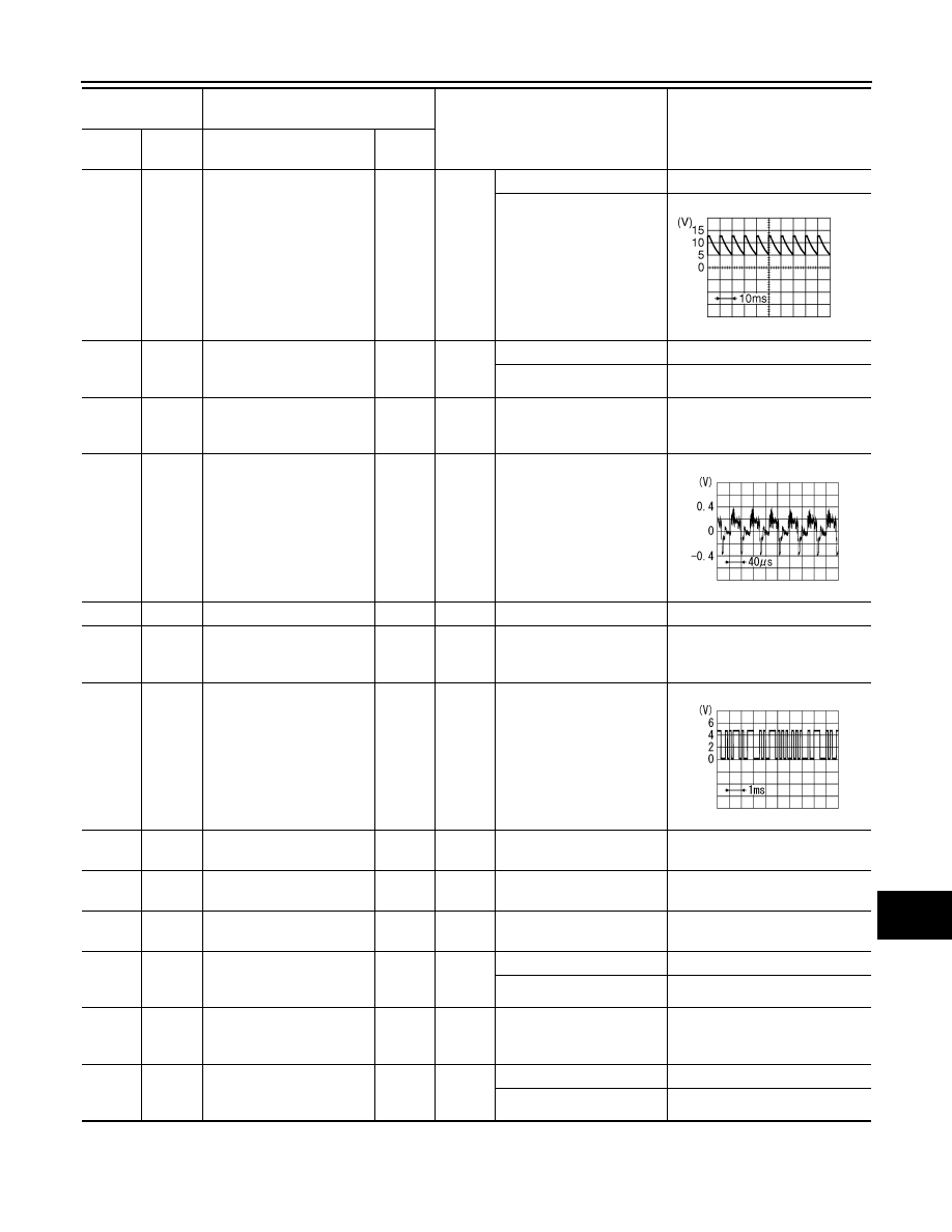
79
(R)
Ground
Illumination signal
Input
Ignition
switch
OFF
Lighting switch is OFF.
0 V
Lighting switch is ON.
12.0 V
80
(G)
Ground
Ignition signal
Input
Ignition
switch
ON
—
Battery voltage
81
(O)
Ground
Reverse signal
Input
Ignition
switch
ON
R position
12.0 V
Other than R position
0 V
Terminal
(Wire color)
Description
Condition
Reference value
(Approx.)
+
–
Signal name
Input/
Output
JPMIA0594GB
SKIB2251J
PKIB5039J
AV-406
< ECU DIAGNOSIS INFORMATION >
[NAVIGATION (TWIN MONITOR)]
AV CONTROL UNIT
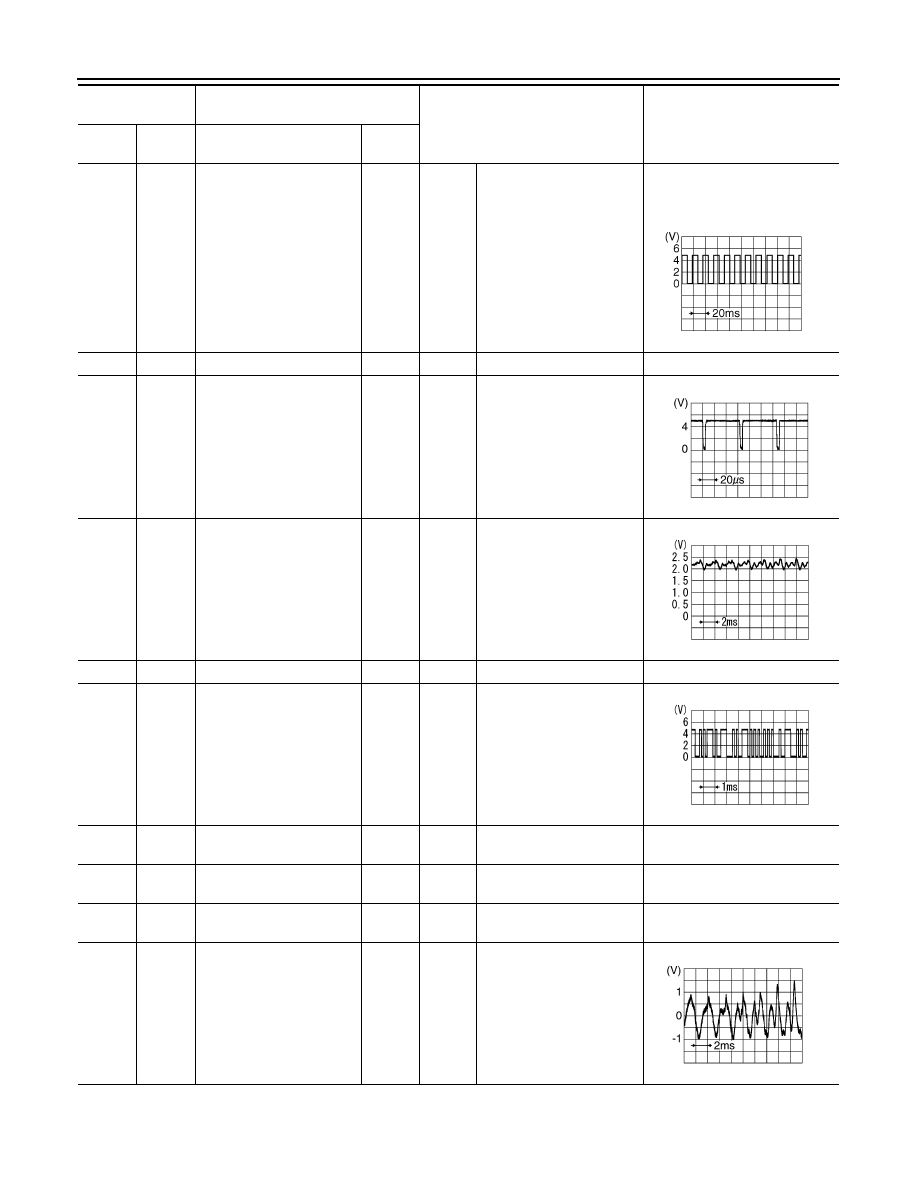
82
(R)
Ground
Vehicle speed signal (8-
pulse)
Input
Ignition
switch
ON
When vehicle speed is ap-
prox. 40 km/h (25 MPH)
NOTE:
Maximum voltage may be 12.0 V
due to specifications (connected
units).
83
—
Shield
—
—
—
—
84
(W)
Ground
Composite image synchro-
nizing signal
Output
Ignition
switch
ON
—
87
(R)
71
Microphone signal
Input
Ignition
switch
ON
Give a voice
88
—
Shield
—
—
—
—
89
(G)
Ground
Communication signal
(DISP
→
CONT)
Input
Ignition
switch
ON
When adjusting display
brightness.
90
(L)
—
CAN–H
Input/
Output
—
—
—
91
(SB)
—
AV communication signal
(H)
Input/
Output
—
—
—
92
(SB)
—
AV communication signal
(H)
Input/
Output
—
—
—
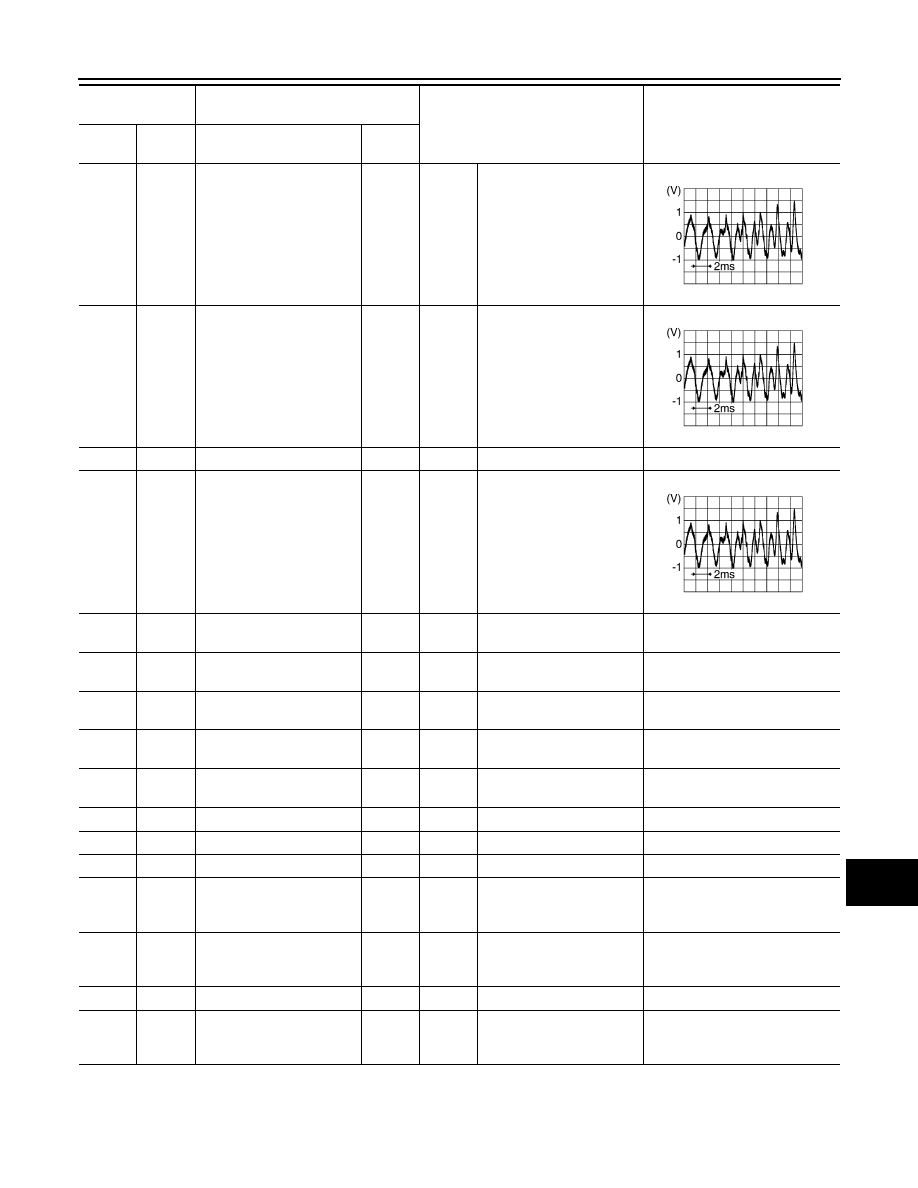
104
(W)
119
(B)
AUX sound signal LH
Input
Ignition
switch
ON
When AUX mode is select-
ed.
Terminal
(Wire color)
Description
Condition
Reference value
(Approx.)
+
–
Signal name
Input/
Output
SKIA6649J
SKIB0825E
PKIB5037J
PKIB5039J
SKIB3609E
AV
AV CONTROL UNIT
AV-407
< ECU DIAGNOSIS INFORMATION >
[NAVIGATION (TWIN MONITOR)]
C
D
E
F
G
H
I
J
K
L
M
B
A
O
P
106
(L)
120
(P)
Headphone sound signal
LH
output
Ignition
switch
ON
Headphone sound output.
107
(BR)
121
(GR)
Headphone sound signal
RH
output
Ignition
switch
ON
Headphone sound output.
117
—
Shield
—
—
—
—
118
(R)
119
(B)
AUX sound signal RH
Input
Ignition
switch
ON
When AUX mode is select-
ed.
122
(B)
—
Shield
—
—
—
—
129
(G)
—
USB ground
—
—
—
—
130
(R)
—
USB D
−
signal
Input/
Output
—
—
—
131
(W)
—
V BUS signal
Output
—
—
—
132
(L)
—
USB D+ signal
Input/
Output
—
—
—
133
—
Shield
—
—
—
—
150
—
FM sub
Input
—
—
—
151
—
AM-FM main
Input
—
—
—
152
Ground
Antenna amp. ON signal
Input
Ignition
switch
ON
—
12.0 V
153
Ground
GPS antenna signal
Input
Ignition
switch
ACC
Not connected GPS anten-
na connector.
5.0 V
154
—
Shield
—
—
—
—
157
Ground
RGB digital image signal
(
−
)
Output
Ignition
switch
ON
Not connected connector.
3.0 V
Terminal
(Wire color)
Description
Condition
Reference value
(Approx.)
+
–
Signal name
Input/
Output
SKIB3609E
SKIB3609E
SKIB3609E
AV-408
< ECU DIAGNOSIS INFORMATION >
[NAVIGATION (TWIN MONITOR)]
AV CONTROL UNIT
Fail-Safe
INFOID:0000000005474746
When the ambiance temperature becomes extremely low or extremely high, AV control unit displays the mes-
sage and limits the AV control unit function.
FAIL-SAFE CONDITIONS
When the ambiance temperature is
−
20
°
C (
−
4
°
F) or lower, or when it is 70
°
C (158
°
F) or higher
Display
The messages displayed on fail-safe conditions are as shown below:
DESCRIPTION OF CONTROLS
Ability Operation Mode
There is an ability operation mode for Fail-safes due to low or high ambiance temperature.
If HDD data can be read, fail-safe is shown, then normal displays are displayed only for functions which can be
operated.
RELEASE CONDITIONS OF FAIL-SAFE
Fail-safe is released on following conditions and normal mode is restored.
When The Temperature of HDD Is Low or High
If the ambient temperature becomes out of fail-safe condition range, normal mode is restored.
DTC Index
INFOID:0000000005511847
SELF-DIAGNOSIS RESULTS DISPLAY ITEM
158
Ground
RGB digital image signal
(+)
Output
Ignition
switch
ON
Not connected connector.
3.0 V
159
Ground
Satellite antenna signal
Input
Ignition
switch
ACC
Not connected to satellite
antenna connector.
4.0 V
Terminal
(Wire color)
Description
Condition
Reference value
(Approx.)
+
–
Signal name
Input/
Output
Fail-safe mode
Display (display of the fail-safe condition)
When HDD temperature is low
HDD system is experiencing problems due to extreme low temperature.
Normal operation will resume when temperature rises.
When HDD temperature is high
HDD system is experiencing problems due to extreme high temperature.
Normal operation will resume when temperature drops.
Function
When Fail-safe Function is activated
Air conditioner
Operation
Only multifunction switch (preset switch) can be operated.
Display
• LED of multifunction switch (preset switch) illuminates.
• Aimed temperature, blow angle, and flow rate are displayed in simplified mode.
Audio
Operation
Only ON/OFF and volume control operations by multifunction switch (preset switch) are possible.
Display
No display (“Fail-safe mode” is displayed)
Camera
Operation
Image tone cannot be controlled.
Display
Cannot be superimposed. (warning display, tone control display)
Hands-free phone
Operation
Cannot be operated.
Navigation
Operation
Cannot be operated.
Self diagnosis
The display in simplified mode of fail-safe condition
CONSULT-III diagnosis
Cannot be operated.
Нет комментариевНе стесняйтесь поделиться с нами вашим ценным мнением.
Текст