Infiniti FX35, FX50 (S51). Manual — part 104
AV
DIAGNOSIS SYSTEM (AROUND VIEW MONITOR CONTROL UNIT)
AV-189
< SYSTEM DESCRIPTION >
[NAVIGATION (SINGLE MONITOR)]
C
D
E
F
G
H
I
J
K
L
M
B
A
O
P
DIAGNOSIS SYSTEM (AROUND VIEW MONITOR CONTROL UNIT)
On Board Diagnosis Function
INFOID:0000000005511924
The diagnosis function of around view monitor control unit is displayed when selecting “Camera Cont.” of Con-
firmation/Adjustment mode in the multi AV system.
Around view monitor control unit diagnosis item
CAUTION:
*: Never perform other operations for approximately 10 seconds after performing "Initialize Camera
Image Calibration".
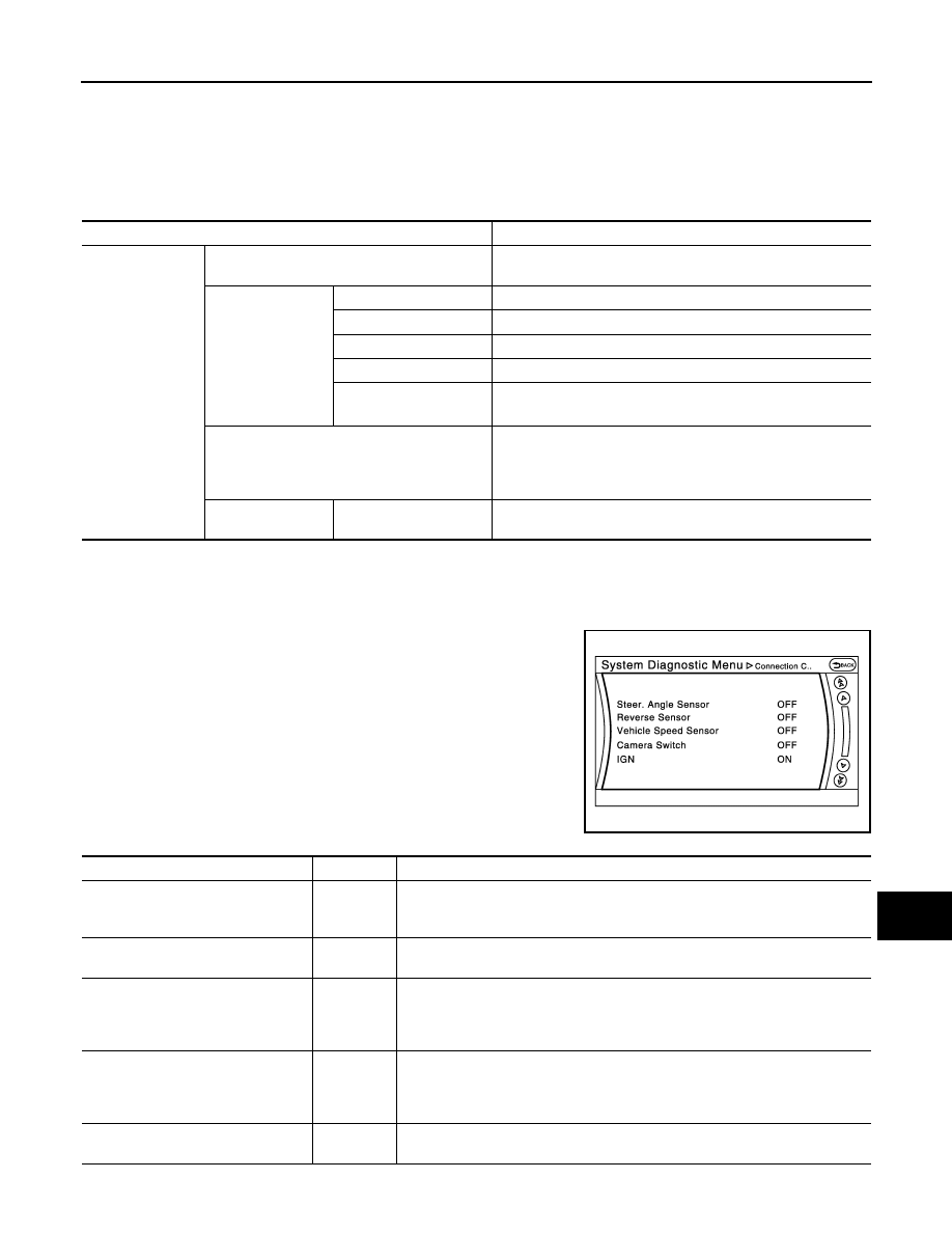
Connection Confirmation
The status of signals inputted to around view monitor control unit can
be checked.
Connection Confirmation item list
AV control unit Confirmation/Adjustment mode
Function
Camera Cont.
Connection Confirmation
The status of signals input to around view monitor control unit
can be checked.
Calibrating Cam-
era Image
Rear Camera
Performs the calibration of rear camera.
Pass-Side Camera
Performs the calibration of side camera RH.
Front Camera
Performs the calibration of front camera.
Dr-Side Camera
Performs the calibration of side camera LH.
Initialize Camera Image
Calibration
*
The calibration can be initialized to NISSAN factory shipment
condition.
Fine Tuning of Birds-Eye View
• The confirmation and adjustment of the difference between
each camera can be performed.
• The system changes to the ZOOM function by the operation
of shift and the ZOOM ratio of each camera can be changed.
Correct Draw Line
of Wide View
Rear-Wide View
The position of rear wide view guideline can be changed.
JSNIA2277ZZ
Diagnosis item
Display
Description
Steer. Angle Sensor
ON/OFF
• Input status of steering angle sensor is displayed by ON/OFF.
• When all of steering signals 1, 2, and 3 are input, it is turned ON. It remains
ON until connection confirmation mode is stopped.
Reverse Sensor
ON/OFF
Input status of reverse signal inputted to around view monitor control unit is dis-
played by ON/OFF in real time.
Vehicle Speed Sensor
ON/OFF
• Input status of vehicle speed signal inputted to around view monitor control
unit is displayed by ON/OFF.
• When the vehicle speed signal is input, it is turned ON. It remains ON until con-
nection confirmation mode is stopped.
Camera Switch
ON/OFF
• The status of camera switch signal received via AV communication from NAVI
control unit is displayed by ON/OFF.
• When the camera switch signal is received once, it is turned ON. It remains
ON until connection confirmation mode is stopped.
IGN
ON/OFF
Input status of ignition signal inputted to around view monitor control unit is dis-
played by ON/OFF in real time.
AV-190
< SYSTEM DESCRIPTION >
[NAVIGATION (SINGLE MONITOR)]
DIAGNOSIS SYSTEM (AROUND VIEW MONITOR CONTROL UNIT)
Calibrating Camera Image
• Perform the calibration of camera image caused by the incorrect
mounting position of each camera, etc. Always perform calibration
after performing the following work.
- When each camera or each camera mount (door mirror, front grille,
etc.) is removed
- When replacing around view monitor control unit
• When performing the calibration initialization, it can be set to the
NISSAN factory shipment condition.
Refer to
AV-245, "CALIBRATING CAMERA IMAGE (AROUND VIEW
for the calibration procedure.
Calibrating Camera Image item
ILL
ON/OFF
Input status of illumination signal inputted to around view monitor control unit is
displayed by ON/OFF in real time.
Type of Steer. Angle Sensor
Abslt.
The input type of steering angle sensor is displayed. (“Abslt.” is displayed on this
model.)
Type of Steer. Gear ratio
1
The type of steering gear ratio is displayed. (“1” is displayed on this model.)
Left or Right Steer.
Right/Left
The steering position is displayed.
Rear Camera Image Output signal
OK/NG
The input status of rear camera image signal is displayed by OK/NG in real time.
Rear Camera COMM Status
OK/NG
The communication status with rear camera is displayed by OK/NG in real time.
Rear Camera COMM Line
OK/NG
The status of communication line with rear camera is displayed by OK/NG in real
time.
Front Camera Image Output signal
OK/NG
The input status of front camera image signal is displayed by OK/NG in real time.
Front Camera COMM Status
OK/NG
The communication status with front camera is displayed by OK/NG in real time.
Front Camera COMM Line
OK/NG
The status of communication line with front camera is displayed by OK/NG in real
time.
Pass-Side Camera Image Output sig-
nal
OK/NG
The input status of side camera RH image signal is displayed by OK/NG in real
time.
Pass-Side Camera COMM Status
OK/NG
The communication status with side camera RH is displayed by OK/NG in real
time.
Pass-Side Camera COMM Line
OK/NG
The status of communication line with side camera RH is displayed by OK/NG in
real time.
Dr-Side Camera Image Output signal
OK/NG
The input status of side camera LH image signal is displayed by OK/NG in real
time.
Dr-Side Camera COMM Status
OK/NG
The communication status with side camera LH is displayed by OK/NG in real
time.
Dr-Side Camera COMM Line
OK/NG
The status of communication line with side camera LH is displayed by OK/NG in
real time.
Diagnosis item
Display
Description
JSNIA2379ZZ
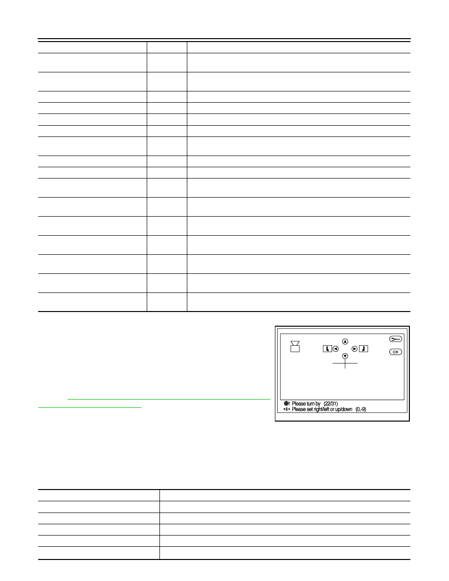
Adjustment range
Rotating direction
: 31 patterns (16 on the center)
Upper/lower direction
:
−
99 – 99
Left/right direction
:
−
99 – 99
Items
Description
Rear Camera
Performs the calibration of rear camera.
Pass-Side Camera
Performs the calibration of side camera RH.
Front Camera
Performs the calibration of front camera.
Dr-Side Camera
Performs the calibration of side camera LH.
Initialize Camera Image Calibration
*
The calibration can be initialized to the factory shipment setting.
AV
DIAGNOSIS SYSTEM (AROUND VIEW MONITOR CONTROL UNIT)
AV-191
< SYSTEM DESCRIPTION >
[NAVIGATION (SINGLE MONITOR)]
C
D
E
F
G
H
I
J
K
L
M
B
A
O
P
CAUTION:
*: Never perform other operations for approximately 10 seconds after performing "Initialize Camera
Image Calibration".
Fine Tuning of Birds-Eye View
• The fine adjustment function of camera calibration can check and
adjust the difference between each camera.
• Fine adjustments can be performed for each camera. Move the
“+”-mark to select the camera by pressing the “CAMERA” switch.
• Perform the adjustment with the center dial and upper/lower/left/
right switches.
CAUTION:
Operate the center dial slowly because the changing of the
screen takes approximately 1 second.
NOTE:
• It can be initialized to the NISSAN factory shipment setting with
“Initialize Camera Image Calibration” of “Calibrating Camera
Image”.
• The adjustment value is cancelled in this mode by performing “Initialize Camera Image Calibration”.
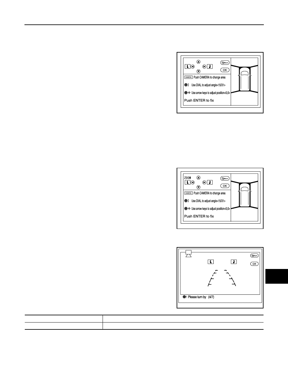
ZOOM function
• The ZOOM ratio of camera can be changed when calibrating the
camera.
• It shifts to ZOOM function mode by shifting the selector lever to a
position other than the “R” position
→
“R” position
→
other than “R”
position in the “Fine Tuning of Birds-Eye View” mode.
• The changing of ZOOM ratio can be performed for each camera.
Move the “+”-mark to select the camera by pressing “CAMERA”
switch and press the left/right switch to change the ZOOM ratio.
NOTE:
• When the position is not correct in “Fine Tuning of Birds-Eye View”
mode, use this "ZOOM" function to adjust it.
• If this function is used, always adjust the upper/lower/left/right posi-
tion again on the “Fine Tuning of Birds-Eye View” screen.
Correct Draw Line of Wide View
The display position of guiding lines when displayed on the rear-wide
view can be changed.
Correct Draw Line of Camera Image item
Adjustment range
Rotating direction
: 31 patterns (16 on the center)
Upper/lower direction
:
−
99 – 99
Left/right direction
:
−
99
−
99
JSNIA2280ZZ
JSNIA2279ZZ
Adjustment range
Rotating direction
: 7 patterns
JSNIA2380ZZ
Items
Description
Rear-Wide View
The position of rear wide view guideline can be changed.

AV-192
< SYSTEM DESCRIPTION >
[NAVIGATION (SINGLE MONITOR)]
DIAGNOSIS SYSTEM (SONAR CONTROL UNIT)
DIAGNOSIS SYSTEM (SONAR CONTROL UNIT)
CONSULT-III Function (SONAR)
INFOID:0000000005511925
DESCRIPTION
CONSULT-III can display each diagnostic item using the diagnostic test modes shown as follows:
ECU IDENTIFICATION
Displays the part number of sonar control unit.
SELF-DIAGNOSTIC RESULTS
For details, refer to
.
DATA MONITOR
ACTIVE TEST
WORK SUPPORT
CORNER SEN DISTANCE SET
Corner sensor warning buzzer distance can be set to 4 phases as follows.
Test mode
Function
Ecu Identification
Sonar control unit part number can be read.
Self Diagnostic Result
Sonar control unit checks the conditions and displays memorized error.
Data Monitor
Sonar control unit input/output data in real time.
Active Test
Gives a drive signal to a load to check the operation.
Work support
Changes setting of each function.
Monitor Item
Display
Description
SONAR OPE
On
Around view monitor is ON. (sonar system is ON)
Off
Around view monitor is OFF. (sonar system is OFF)
BUZZER OUTPUT
On
Buzzer is output condition.
Off
Buzzer is not output condition.
CR SEN [FL]
CR SEN [FR]
CR SEN [RL]
CR SEN [RR]
ERROR
When a sensor is abnormal.
LV.0
When a sensor is not detection.
LV.2
The distance between the corner sensor and an obstacle is 60 cm (23.6 in) or more and
less then 70 cm (27.5 in).
LV.3
The distance between the corner sensor and an obstacle is 40 cm (15.7 in) or more and
less then 60 cm (23.6 in).
LV.4
The distance between corner sensor and an obstacle less than 40 cm (15.7 in).
Active test item
Function
BUZZER
This test is able to check buzzer operation.
SONAR SENSOR
This test is able to check each sonar sensor operation.
Work support item
Function
CORNER SEN DISTANCE SET
Corner sensor warning buzzer distance is adjustable to 4 phases.
Warning item
FARTHER
FAR
NORMAL
NEAR
Second warning
70 – 80 cm (27.5 – 31.4 in)
60 – 70 cm (23.6 – 27.5 in)
50 – 60 cm (19.6 – 23.6 in)
40 – 50 cm (15.7 – 19.6 in)
Third warning
50 – 70 cm (19.6 – 27.5 in)
40 – 60 cm (15.7 – 23.6 in)
30 – 50 cm (11.8 – 19.6 in)
30 – 40 cm (11.8 – 15.7 in)
Fourth warning
Less than 50 cm (19.6 in)
Less than 40 cm (15.7 in)
Less than 30 cm (11.8 in)
Less than 30 cm (11.8 in)
Нет комментариевНе стесняйтесь поделиться с нами вашим ценным мнением.
Текст