Infiniti FX35, FX50 (S51). Manual — part 103
AV
DIAGNOSIS SYSTEM (AV CONTROL UNIT)
AV-185
< SYSTEM DESCRIPTION >
[NAVIGATION (SINGLE MONITOR)]
C
D
E
F
G
H
I
J
K
L
M
B
A
O
P
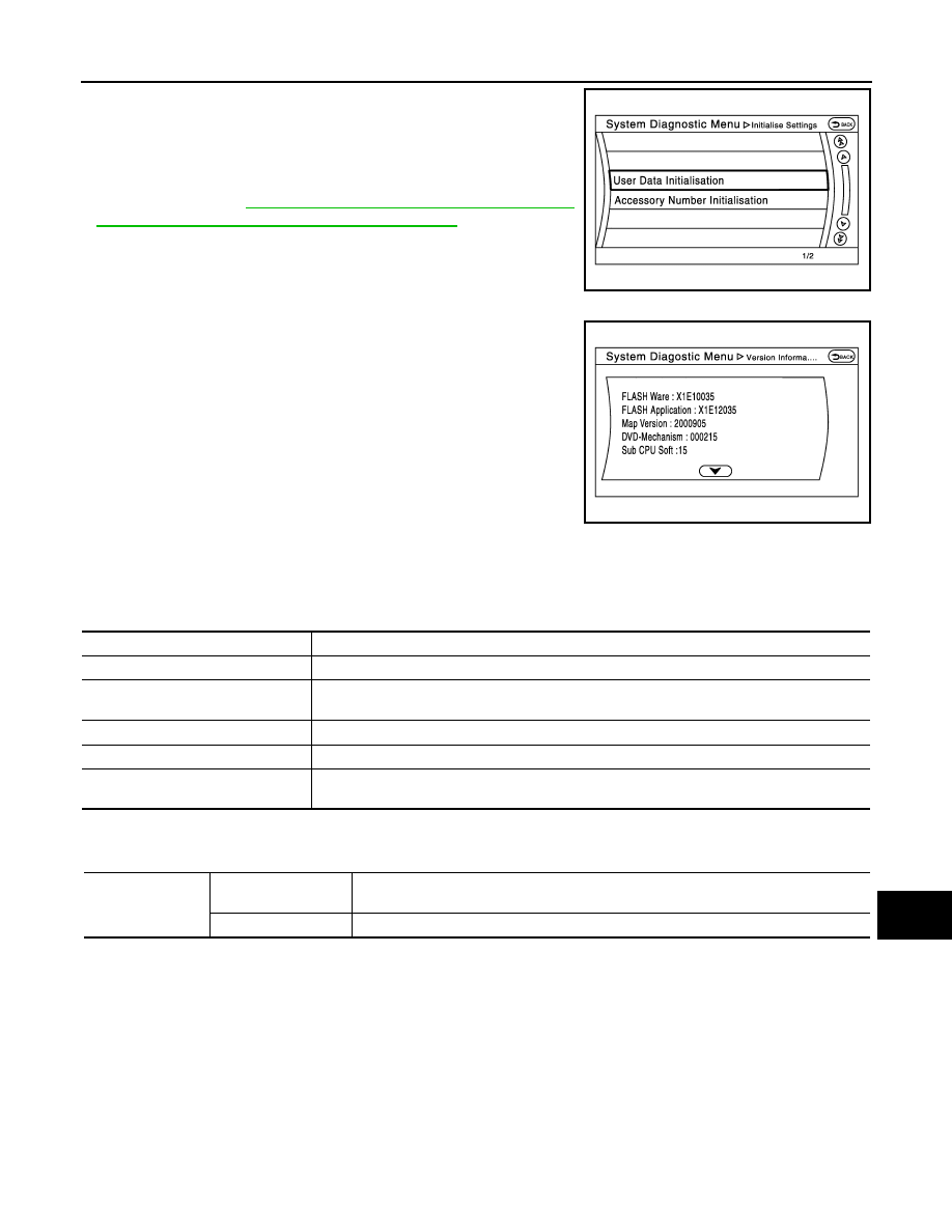
“User Data Initialization” and “Accessory Number Initialization” are
possible.
CAUTION:
• Never perform Accessory Number Initialization except when
configuration is unsuccessful.
• Accessory Number Initialization requires configuration. For
AV-243, "ADDITIONAL SERVICE WHEN
REPLACING AV CONTROL UNIT : Description"
.
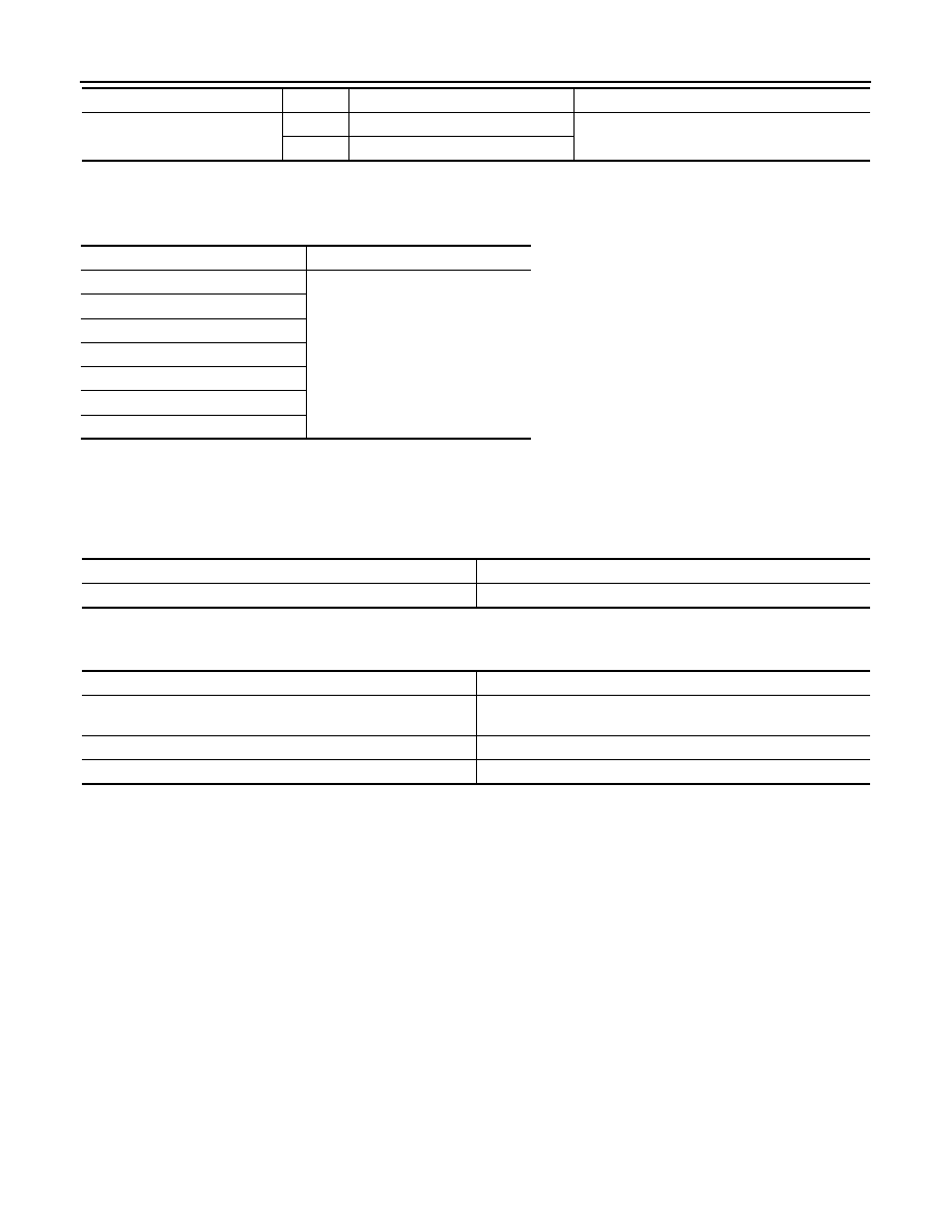
Version Information
Version information of the AV control unit is displayed.
CONSULT - III Function (MULTI AV)
INFOID:0000000005475013
CONSULT-III FUNCTIONS
CONSULT-III performs the following functions via the communication with the AV control unit.
AV COMMUNICATION
When “AV communication” of “CAN Diag Support Monitor” is selected, the following function will be performed.
ECU IDENTIFICATION
The part number of AV control unit is displayed.
SELF DIAGNOSIS RESULT
• In CONSULT-III self-diagnosis, self-diagnosis results and error history are displayed collectively.
• The current malfunction indicates “CRNT”. The past malfunction indicates “PAST”.
• The timing is displayed as “0” if any of the error codes [U1000], [U1010], [U1300] and [U1310] is detected.
The counter increases by 1 if the condition is normal at the next ignition switch ON cycle.
Self-diagnosis Results Display Item
JSNIA2190ZZ
JSNIA2191ZZ
Diagnosis mode
Description
Ecu Identification
The part number of AV control unit can be checked.
Self Diagnostic Result
Performs a diagnosis on the AV control unit and a connection diagnosis for the communication
circuit of the Multi AV system, and displays the current and past malfunctions collectively.
Data Monitor
The diagnosis of vehicle signal that is input to the AV control unit can be performed.
Work Support
Steering angle sensor can be adjusted.
Configuration
• Read and save the vehicle specification.
• Write the vehicle specification when replacing AV control unit.
AV communication
AV&NAVI C/U
Displays the communication status from AV control unit to each unit as well as the error
counter.
AUDIO
Displays the AV control unit communication status and the error counter.

AV-186
< SYSTEM DESCRIPTION >
[NAVIGATION (SINGLE MONITOR)]
DIAGNOSIS SYSTEM (AV CONTROL UNIT)
Error item
Description
Possible malfunction factor/Action to take
CAN COMM CIRCUIT [U1000]
CAN communication malfunction is detect-
ed.
Refer to
.
CONTROL UNIT (CAN) [U1010]
CAN initial diagnosis malfunction is detect-
ed.
Replace the AV control unit if the malfunc-
tion occurs constantly.
CONTROL UNIT (AV) [U1310]
AV communication circuit initial diagnosis
malfunction is detected.
Cont Unit [U1200]
AV control unit malfunction is detected.
GYRO NO CONN [U1201]
G-SENSOR NO CONN [U1202]
CAN CONT [U1216]
BLUETOOTH MODULE [U1217]
SUB CPU CONN [U1228]
iPod CERTIFICATION [U1229]
Built-in AUDIO CONN [U122E]
HDD CONN [U1218]
AV control unit malfunction is detected.
• If the music box function has no mal-
functions, then there is a possibility of
the detection of a temporary malfunc-
tion.
• Replace the AV control unit if the mal-
function occurs constantly.
HDD READ [U1219]
HDD WRITE [U121A]
HDD COMM [U121B]
HDD ACCESS [U121C]
GPS COMM [U1204]
GPS malfunction is detected.
An intermittent error caused by strong ra-
dio interference may be detected unless
any symptom (GPS reception error, etc.)
occurs.
Replace the AV control unit if the malfunc-
tion occurs constantly.
GPS ROM [U1205]
GPS RAM [U1206]
GPS RTC [U1207]
USB CONTROLLER [U1225]
USB connection malfunction is detected.
Check that the connection to the USB con-
nector is normal.
DSP CONN [U121D]
AV control unit malfunction is detected.
• If a disc can be played, then there is a
possibility of the detection of a tempo-
rary malfunction.
• Replace the AV control unit if the mal-
function occurs constantly.
DSP COMM [U121E]
DVD COMM [U1227]
AV control unit malfunction is detected.
• If DVD can be played, then there is a
possibility of the detection of a tempo-
rary malfunction.
• Replace the AV control unit if the mal-
function occurs constantly.
CONFIG UNFINISH [U122A]
The writing of configuration data is incom-
plete.
Write configuration data with CONSULT-
III.
ST ANGLE SEN CALIB [U1232]
Predictive course line center position ad-
justment of the steering angle sensor is in-
complete.
Adjust the predictive course line center po-
sition of the steering angle sensor.
Refer to
STEERING ANGLE SENSOR NEUTRAL
POSITION : Special Repair Requirement"
.
FRONT DISP CONN [U1243]
When either one of the following items are
detected:
• front display unit power supply and
ground circuits malfunction is detected.
• communication circuits between AV
control unit and front display unit.
• Front display unit power supply and
ground circuits.
• Communication circuits between AV
control unit and AV front display unit.
GPS ANTENNA CONN [U1244]
GPS antenna connection malfunction is
detected.
Check the connection of the GPS antenna
connector.

AV
DIAGNOSIS SYSTEM (AV CONTROL UNIT)
AV-187
< SYSTEM DESCRIPTION >
[NAVIGATION (SINGLE MONITOR)]
C
D
E
F
G
H
I
J
K
L
M
B
A
O
P
DATA MONITOR
ALL SIGNALS
• Displays the status of the following vehicle signals inputted into the AV control unit.
• For each signal, actual signal can be compared with the condition recognized on the system.
XM ANTENNA CONN [U1258]
Satellite radio antenna connection mal-
function is detected.
Satellite radio antenna disconnection.
USB OVERCURRENT [U1263]
Detection of overcurrent in USB connect-
er.
Check USB harness between the AV con-
trol unit and USB connector.
• AV COMM CIRCUIT [U1300]
• SWITCH CONN [U1240]
When either one of the following items are
detected:
• multifunction switch power supply and
ground circuits are malfunctioning.
• AV communication circuits between AV
control unit and multifunction switch are
malfunctioning.
• Multifunction switch power supply and
ground circuits.
• AV communication circuits between AV
control unit and multifunction switch.
• AV COMM CIRCUIT [U1300]
• AROUND CAMERA CONN [U125B]
When either one of the following items are
detected:
• around view monitor control unit power
supply and ground circuits are malfunc-
tioning.
• AV communication circuits between
multifunction switch and around view
monitor control unit are malfunctioning.
• Around view monitor control unit power
supply and ground circuits.
• AV communication circuits between
multifunction switch and around view
monitor control unit.
• AV COMM CIRCUIT [U1300]
• SONAR CONN [U125C]
When either one of the following items are
detected:
• sonar control unit power supply and
ground circuits are malfunctioning.
• AV communication circuits between AV
control unit and sonar control unit are
malfunctioning.
• Sonar control unit power supply and
ground circuits.
• AV communication circuits between AV
control unit and sonar control unit.
• AV COMM CIRCUIT [U1300]
• SWITCH CONN [U1240]
• AROUND CAMERA CONN [U125B]
AV communication circuits between AV
control unit and multifunction switch are
malfunctioning.
AV communication circuits between AV
control unit and multifunction switch.
Error item
Description
Possible malfunction factor/Action to take
Display Item
Display
Vehicle status
Remarks
VHCL SPD SIG
On
Vehicle speed >0 km/h (0 MPH)
Changes in indication may be delayed. This is
normal.
Off
Vehicle speed =0 km/h (0 MPH)
PKB SIG
On
Parking brake is applied.
Off
Parking brake is released.
ILLUM SIG
On
Block the light beam from the auto
light optical sensor when the light
SW is ON.
—
Off
Expose the auto light optical sensor
to light when the light SW is OFF or
ON.
IGN SIG
On
Ignition switch ON
Off
Ignition switch in ACC position
REV SIG
On
Selector lever in R position
Changes in indication may be delayed. This is
normal.
Off
Selector lever in any position other
than R
SIDE VIEW SW
Off
This item is displayed, but cannot be
monitored.
—
AV-188
< SYSTEM DESCRIPTION >
[NAVIGATION (SINGLE MONITOR)]
DIAGNOSIS SYSTEM (AV CONTROL UNIT)
SELECTION FROM MENU
Allows the technician to select which vehicle signals should be displayed and displays the status of the
selected vehicle signals.
WORK SUPPORT
Adjusts the neutral position of the steering angle sensor.
CAUTION:
For vehicles with VDC, adjust the steering angle sensor neutral position on the ABS actuator control
unit side.
CONFIGURATION
Configuration has three functions as follows.
ROOM LAMP
On
After opening any door; 5 seconds.
Check 10 seconds later, after closing all doors.
Off
Except for above.
Display Item
Display
Vehicle status
Remarks
Item to be selected
Description
VHCL SPD SIG
The same as when “ALL SIGNALS”
is selected.
PKB SIG
ILLUM SIG
IGN SIG
REV SIG
SIDE VIEW SW
ROOM LAMP
Item
Description
ST ANGLE SENSOR ADJUSTMENT
Adjusts the neutral position of the steering angle sensor.
Function
Description
READ CONFIGURATION
• Reads the vehicle configuration of current AV control unit.
• Saves the read vehicle configuration.
WRITE CONFIGURATION-Manual selection
Writes the vehicle configuration with manual selection.
WRITE CONFIGURATION-Config file
Writes the vehicle configuration with saved data.
Нет комментариевНе стесняйтесь поделиться с нами вашим ценным мнением.
Текст