Infiniti FX35, FX50 (S51). Manual — part 1282
LAN-70
< DTC/CIRCUIT DIAGNOSIS >
[CAN]
TCM BRANCH LINE CIRCUIT
TCM BRANCH LINE CIRCUIT
Diagnosis Procedure
INFOID:0000000005241909
1.
CHECK CONNECTOR
1.
Turn the ignition switch OFF.
2.
Disconnect the battery cable from the negative terminal.
3.
Check the following terminals and connectors for damage, bend and loose connection (unit side and con-
nector side).
-
A/T assembly
-
Harness connector F103
-
Harness connector M116
Is the inspection result normal?
YES
>> GO TO 2.
NO
>> Repair the terminal and connector.
2.
CHECK HARNESS FOR OPEN CIRCUIT
1.
Disconnect the connector of A/T assembly.
2.
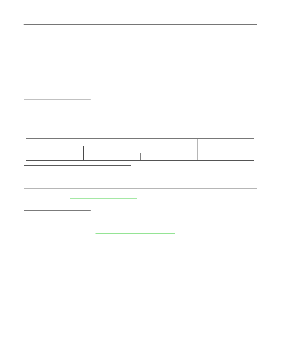
Check the resistance between the A/T assembly harness connector terminals.
Is the measurement value within the specification?
YES
>> GO TO 3.
NO
>> Repair the TCM branch line.
3.
CHECK POWER SUPPLY AND GROUND CIRCUIT
Check the power supply and the ground circuit of the TCM. Refer to the following.
• VQ engine models:
• VK engine models:
Is the inspection result normal?
YES (Present error)>>Replace the control valve with TCM. (Replace A/T assembly if control valve with TCM
is not listed in the latest parts list.) Refer to the following.
• VQ engine models:
TM-11, "Component Parts Location"
• VK engine models:
TM-193, "Component Parts Location"
YES (Past error)>>Error was detected in the TCM branch line.
NO
>> Repair the power supply and the ground circuit.
A/T assembly harness connector
Resistance (
Ω
)
Connector No.
Terminal No.
F51
3
8
Approx. 54 – 66

LAN
A-BAG BRANCH LINE CIRCUIT
LAN-71
< DTC/CIRCUIT DIAGNOSIS >
[CAN]
C
D
E
F
G
H
I
J
K
L
B
A
O
P
N
A-BAG BRANCH LINE CIRCUIT
Diagnosis Procedure
INFOID:0000000005241910
WARNING:
• Before servicing, turn ignition switch OFF, disconnect battery negative terminal, and wait 3 minutes
or more. (To discharge backup capacitor.)
• Never use unspecified tester or other measuring device.
1.
CHECK CONNECTOR
1.
Turn the ignition switch OFF.
2.
Disconnect the battery cable from the negative terminal.
3.
Check the terminals and connectors of the air bag diagnosis sensor unit for damage, bend and loose con-
nection (unit side and connector side).
Is the inspection result normal?
YES
>> GO TO 2.
NO
>> Replace the main harness.
2.
CHECK AIR BAG DIAGNOSIS SENSOR UNIT
Check the air bag diagnosis sensor unit. Refer to
Is the inspection result normal?
YES
>> Replace the main harness.
NO
>> Replace parts whose air bag system has a malfunction.
LAN-72
< DTC/CIRCUIT DIAGNOSIS >
[CAN]
AV BRANCH LINE CIRCUIT
AV BRANCH LINE CIRCUIT
Diagnosis Procedure
INFOID:0000000005241911
1.
CHECK CONNECTOR
1.
Turn the ignition switch OFF.
2.
Disconnect the battery cable from the negative terminal.
3.
Check the terminals and connectors of the AV control unit for damage, bend and loose connection (unit
side and connector side).
Is the inspection result normal?
YES
>> GO TO 2.
NO
>> Repair the terminal and connector.
2.
CHECK HARNESS FOR OPEN CIRCUIT
1.
Disconnect the connector of AV control unit.
2.
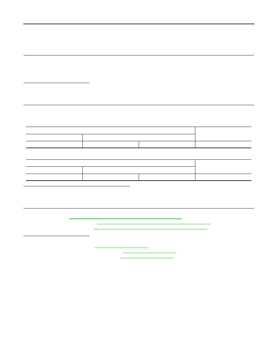
Check the resistance between the AV control unit harness connector terminals.
-
Models with navigation system
-
Models without navigation system
Is the measurement value within the specification?
YES
>> GO TO 3.
NO
>> Repair the AV control unit branch line.
3.
CHECK POWER SUPPLY AND GROUND CIRCUIT
Check the power supply and the ground circuit of the AV control unit. Refer to the following.
• Without navigation:
AV-101, "AV CONTROL UNIT : Diagnosis Procedure"
• With navigation (Single monitor):
AV-291, "AV CONTROL UNIT : Diagnosis Procedure"
• With navigation (Twin monitor):
AV-510, "AV CONTROL UNIT : Diagnosis Procedure"
Is the inspection result normal?
YES (Present error)>>Replace the AV control unit. Refer to the following.
• Without navigation:
• With navigation (Single monitor):
• With navigation (Twin monitor):
YES (Past error)>>Error was detected in the AV control unit branch line.
NO
>> Repair the power supply and the ground circuit.
AV control unit harness connector
Resistance (
Ω
)
Connector No.
Terminal No.
M210
90
74
Approx. 54 – 66
AV control unit harness connector
Resistance (
Ω
)
Connector No.
Terminal No.
M204
81
80
Approx. 54 – 66
LAN
BCM BRANCH LINE CIRCUIT
LAN-73
< DTC/CIRCUIT DIAGNOSIS >
[CAN]
C
D
E
F
G
H
I
J
K
L
B
A
O
P
N
BCM BRANCH LINE CIRCUIT
Diagnosis Procedure
INFOID:0000000005241912
1.
CHECK CONNECTOR
1.
Turn the ignition switch OFF.
2.
Disconnect the battery cable from the negative terminal.
3.
Check the terminals and connectors of the BCM for damage, bend and loose connection (unit side and
connector side).
Is the inspection result normal?
YES
>> GO TO 2.
NO
>> Repair the terminal and connector.
2.
CHECK HARNESS FOR OPEN CIRCUIT
1.
Disconnect the connector of BCM.
2.
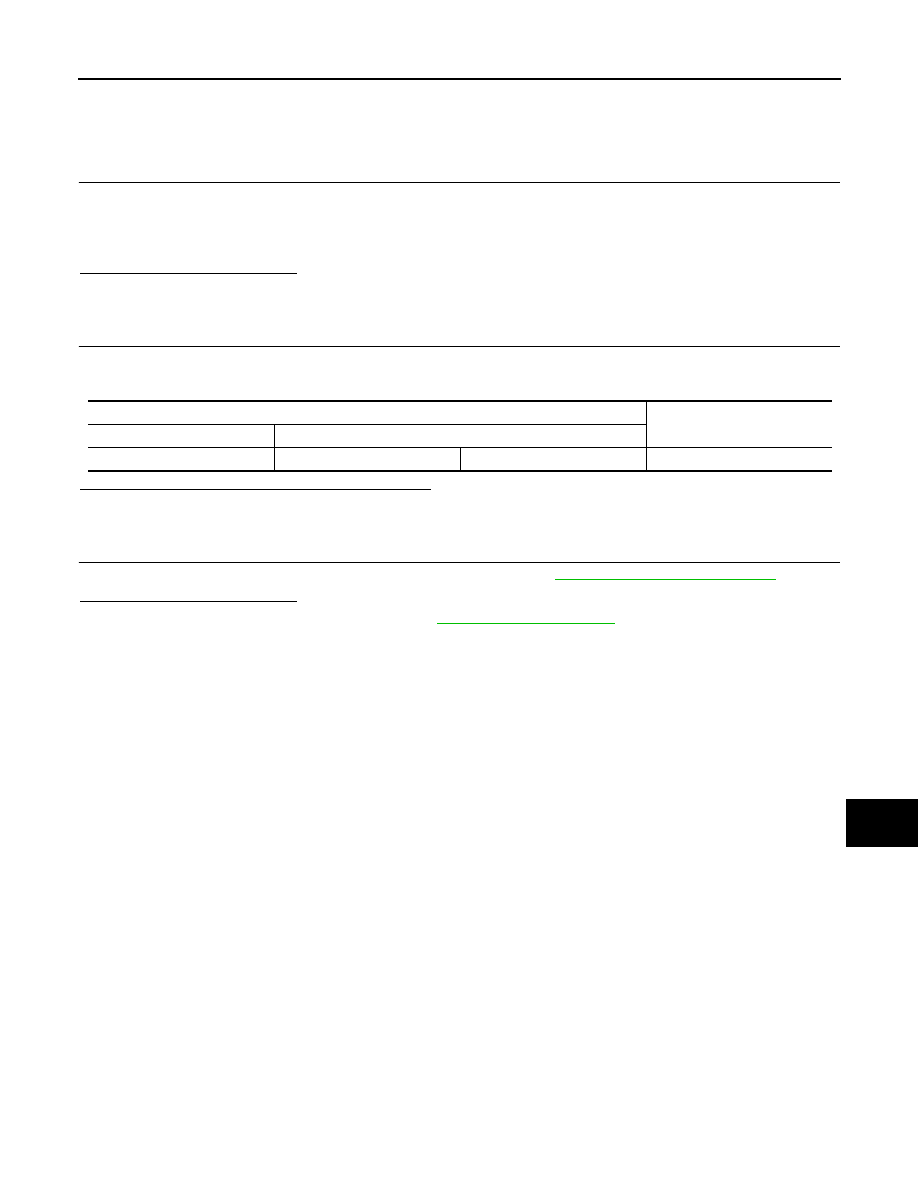
Check the resistance between the BCM harness connector terminals.
Is the measurement value within the specification?
YES
>> GO TO 3.
NO
>> Repair the BCM branch line.
3.
CHECK POWER SUPPLY AND GROUND CIRCUIT
Check the power supply and the ground circuit of the BCM. Refer to
Is the inspection result normal?
YES (Present error)>>Replace the BCM. Refer to
.
YES (Past error)>>Error was detected in the BCM branch line.
NO
>> Repair the power supply and the ground circuit.
BCM harness connector
Resistance (
Ω
)
Connector No.
Terminal No.
M122
91
90
Approx. 54 – 66
Нет комментариевНе стесняйтесь поделиться с нами вашим ценным мнением.
Текст