Infiniti FX35, FX50 (S51). Manual — part 1280

LAN-62
< DTC/CIRCUIT DIAGNOSIS >
[CAN]
MAIN LINE BETWEEN ADP AND CGW CIRCUIT
MAIN LINE BETWEEN ADP AND CGW CIRCUIT
Diagnosis Procedure
INFOID:0000000005241898
1.
CHECK CONNECTOR
1.
Turn the ignition switch OFF.
2.
Disconnect the battery cable from the negative terminal.
3.
Check the following terminals and connectors for damage, bend and loose connection (connector side
and harness side).
-
Harness connector B1
-
Harness connector M7
Is the inspection result normal?
YES
>> GO TO 2.
NO
>> Repair the terminal and connector.
2.
CHECK HARNESS CONTINUITY (OPEN CIRCUIT)
1.
Disconnect the harness connectors B1 and M7.
2.
Check the continuity between the harness connector terminals.
Is the inspection result normal?
YES
>> GO TO 3.
NO
>> Repair the main line between the driver seat control unit and the harness connector B1.
3.
CHECK HARNESS CONTINUITY (OPEN CIRCUIT)
1.
Disconnect the connector of CAN gateway.
2.
Check the continuity between the harness connector M7 and the CAN gateway harness connector.
Is the inspection result normal?
YES (Present error)>>Check CAN system type decision again.
YES (Past error)>>Error was detected in the main line between the driver seat control unit and the CAN
gateway.
NO
>> Repair the main line between the harness connector M7 and the CAN gateway.
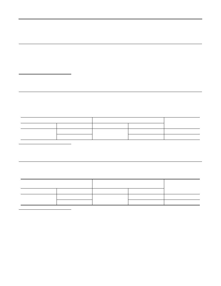
Connector No.
Terminal No.
Continuity
B1
82
80
Existed
83
81
Existed
Harness connector
CAN gateway harness connector
Continuity
Connector No.
Terminal No.
Connector No.
Terminal No.
M7
82
M125
1
Existed
83
7
Existed

LAN
MAIN LINE BETWEEN CGW AND ABS CIRCUIT
LAN-63
< DTC/CIRCUIT DIAGNOSIS >
[CAN]
C
D
E
F
G
H
I
J
K
L
B
A
O
P
N
MAIN LINE BETWEEN CGW AND ABS CIRCUIT
Diagnosis Procedure
INFOID:0000000005241899
1.
CHECK CONNECTOR
1.
Turn the ignition switch OFF.
2.
Disconnect the battery cable from the negative terminal.
3.
Check the following terminals and connectors for damage, bend and loose connection (connector side
and harness side).
-
Harness connector M6
-
Harness connector E106
Is the inspection result normal?
YES
>> GO TO 2.
NO
>> Repair the terminal and connector.
2.
CHECK HARNESS CONTINUITY (OPEN CIRCUIT)
1.
Disconnect the following harness connectors.
-
CAN gateway
-
Harness connectors M6 and E106
2.
Check the continuity between the CAN gateway harness connector and the harness connector.
Is the inspection result normal?
YES
>> GO TO 3.
NO
>> Repair the main line between the CAN gateway and the harness connector M6.
3.
CHECK HARNESS CONTINUITY (OPEN CIRCUIT)
1.
Disconnect the connector of ABS actuator and electric unit (control unit).
2.
Check the continuity between the harness connector and the ABS actuator and electric unit (control unit)
harness connector.
Is the inspection result normal?
YES (Present error)>>Check CAN system type decision again.
YES (Past error)>>Error was detected in the main line between the CAN gateway and the ABS actuator and
electric unit (control unit).
NO
>> Repair the main line between the harness connector E106 and the ABS actuator and electric unit
(control unit).
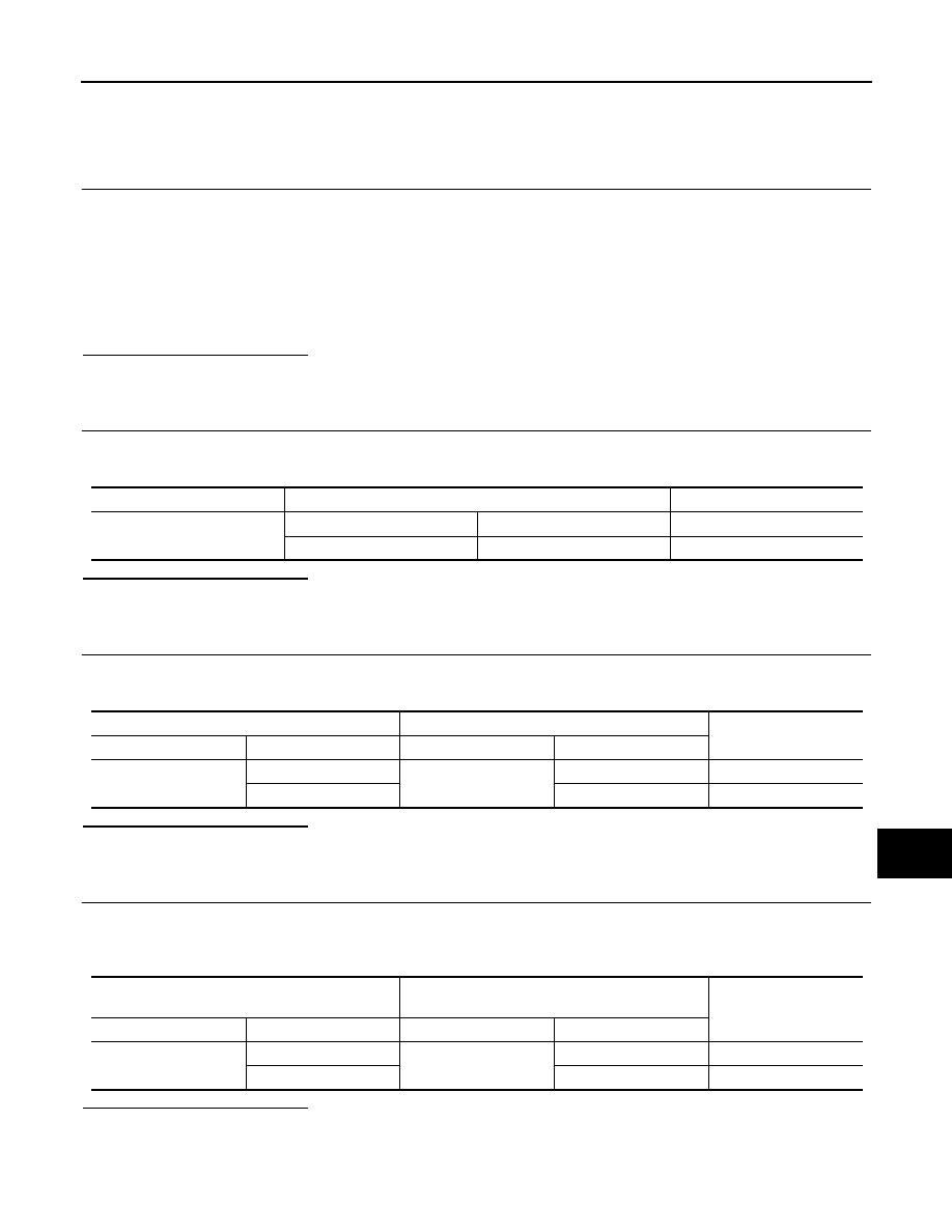
CAN gateway harness connector
Harness connector
Continuity
Connector No.
Terminal No.
Connector No.
Terminal No.
M125
1
M6
47
Existed
7
48
Existed
Harness connector
ABS actuator and electric unit (control unit)
harness connector
Continuity
Connector No.
Terminal No.
Connector No.
Terminal No.
E106
47
E41
35
Existed
48
14
Existed
LAN-64
< DTC/CIRCUIT DIAGNOSIS >
[CAN]
MAIN LINE BETWEEN M&A AND ABS CIRCUIT
MAIN LINE BETWEEN M&A AND ABS CIRCUIT
Diagnosis Procedure
INFOID:0000000005241900
1.
CHECK CONNECTOR
1.
Turn the ignition switch OFF.
2.
Disconnect the battery cable from the negative terminal.
3.
Check the following terminals and connectors for damage, bend and loose connection (connector side
and harness side).
-
Harness connector M6
-
Harness connector E106
Is the inspection result normal?
YES
>> GO TO 2.
NO
>> Repair the terminal and connector.
2.
CHECK HARNESS CONTINUITY (OPEN CIRCUIT)
1.
Disconnect the following harness connectors.
-
Unified meter and A/C amp.
-
Harness connectors M6 and E106
2.
Check the continuity between the unified meter and A/C amp. harness connector and the harness con-
nector.
Is the inspection result normal?
YES
>> GO TO 3.
NO
>> Repair the main line between the unified meter and A/C amp. and the harness connector M6.
3.
CHECK HARNESS CONTINUITY (OPEN CIRCUIT)
1.
Disconnect the connector of ABS actuator and electric unit (control unit).
2.
Check the continuity between the harness connector and the ABS actuator and electric unit (control unit)
harness connector.
Is the inspection result normal?
YES (Present error)>>Check CAN system type decision again.
YES (Past error)>>Error was detected in the main line between the unified meter and A/C amp. and the ABS
actuator and electric unit (control unit).
NO
>> Repair the main line between the harness connector E106 and the ABS actuator and electric unit
(control unit).
Unified meter and A/C amp. harness connector
Harness connector
Continuity
Connector No.
Terminal No.
Connector No.
Terminal No.
M67
56
M6
47
Existed
72
48
Existed
Harness connector
ABS actuator and electric unit (control unit)
harness connector
Continuity
Connector No.
Terminal No.
Connector No.
Terminal No.
E106
47
E41
35
Existed
48
14
Existed
LAN
MAIN LINE BETWEEN ADP AND ABS CIRCUIT
LAN-65
< DTC/CIRCUIT DIAGNOSIS >
[CAN]
C
D
E
F
G
H
I
J
K
L
B
A
O
P
N
MAIN LINE BETWEEN ADP AND ABS CIRCUIT
Diagnosis Procedure
INFOID:0000000005241901
1.
CHECK CONNECTOR
1.
Turn the ignition switch OFF.
2.
Disconnect the battery cable from the negative terminal.
3.
Check the following terminals and connectors for damage, bend and loose connection (connector side
and harness side).
-
Harness connector B1
-
Harness connector M7
-
Harness connector M6
-
Harness connector E106
Is the inspection result normal?
YES
>> GO TO 2.
NO
>> Repair the terminal and connector.
2.
CHECK HARNESS CONTINUITY (OPEN CIRCUIT)
1.
Disconnect the harness connectors B1 and M7.
2.
Check the continuity between the harness connector terminals.
Is the inspection result normal?
YES
>> GO TO 3.
NO
>> Repair the main line between the driver seat control unit and the harness connector B1.
3.
CHECK HARNESS CONTINUITY (OPEN CIRCUIT)
1.
Disconnect the harness connectors M6 and E106.
2.
Check the continuity between the harness connectors.
Is the inspection result normal?
YES
>> GO TO 4.
NO
>> Repair the main line between the harness connectors M7 and M6.
4.
CHECK HARNESS CONTINUITY (OPEN CIRCUIT)
1.
Disconnect the connector of ABS actuator and electric unit (control unit).
2.
Check the continuity between the harness connector and the ABS actuator and electric unit (control unit)
harness connector.
Is the inspection result normal?
YES (Present error)>>Check CAN system type decision again.
YES (Past error)>>Error was detected in the main line between the driver seat control unit and the ABS actu-
ator and electric unit (control unit).
Connector No.
Terminal No.
Continuity
B1
82
80
Existed
83
81
Existed
Harness connector
Harness connector
Continuity
Connector No.
Terminal No.
Connector No.
Terminal No.
M7
82
M6
47
Existed
83
48
Existed
Harness connector
ABS actuator and electric unit (control unit)
harness connector
Continuity
Connector No.
Terminal No.
Connector No.
Terminal No.
E106
47
E41
35
Existed
48
14
Existed
Нет комментариевНе стесняйтесь поделиться с нами вашим ценным мнением.
Текст