Infiniti FX35, FX50 (S51). Manual — part 1837

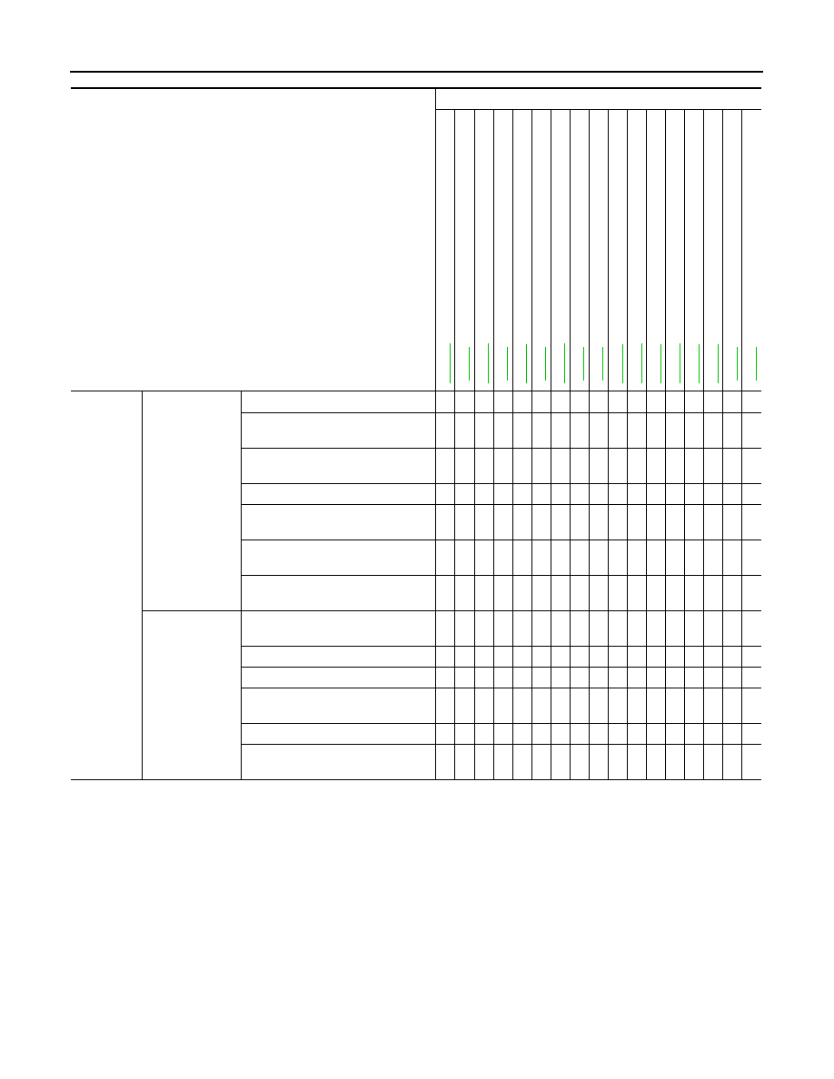
SYSTEM SYMPTOM
TM-155
< SYMPTOM DIAGNOSIS >
[7AT: RE7R01A (VQ35HR)]
C
E
F
G
H
I
J
K
L
M
A
B
TM
N
O
P
Func-
tion trou-
ble
Poor
power
trans-
mis-
sion
Slip
With selector lever in
“D” position, accelera-
tion is extremely poor.
5
3
3
3
4
1
1
1
2
With selector lever in
“R” position, accelera-
tion is extremely poor.
5
3
3
3
4
1
1
1
2
While starting off by
accelerating in 1GR,
engine races.
3
3
3
4
1
1
1
2
While accelerating in
2GR, engine races.
3
3
3
4
1
1
1
1
2
While accelerating in
3GR, engine races.
3
3
3
4
1
1
1
1
2
While accelerating in
4GR, engine races.
3
3
3
4
1
1
1
1
2
While accelerating in
5GR, engine races.
3
3
3
4
1
1
1
1
1
2
While accelerating in
6GR, engine races.
3
3
3
4
1
1
1
1
1
2
While accelerating in
7GR, engine races.
3
3
3
4
1
1
1
1
1
2
Lock-up
3
3
3
4
1
1
2
No creep at all.
1
1
1
1
1
1
1
1
1
Extremely large
creep.
1
Symptom
Diagnostic item
Con
tro
l l
ink
ag
e
Ou
tp
ut
sp
ee
d s
en
s
o
r
En
gin
e sp
ee
d
s
ig
na
l
Inp
ut
sp
ee
d se
n
s
or
A/
T f
lui
d t
em
pe
rat
u
re se
ns
or
T
ran
sm
is
si
o
n
ran
g
e
swi
tch
Ma
nu
al
mo
de
swi
tch
Li
n
e
pre
ss
u
re
so
le
no
id
va
lv
e
T
o
rqu
e
c
o
n
v
e
rte
r cl
utch
so
le
no
id
va
lv
e
Lo
w bra
ke
so
le
no
id
va
lv
e
F
ron
t
b
rak
e so
len
oi
d v
al
v
e
Hi
gh
an
d lo
w rev
e
rs
e cl
u
tc
h
s
o
le
n
o
id
v
a
lve
In
pu
t clu
tch
sol
eno
id
valve
Dire
ct
cl
utc
h
so
le
no
id
va
lv
e
2
346
b
rak
e s
o
len
oi
d v
al
v
e
An
ti-i
nte
rlo
ck
s
o
le
no
id
va
lv
e
CAN communication
TM
-1
6
7
TM-7
6
TM-7
8
TM-7
4
TM-7
2
TM-7
1
T
M
-111
TM-9
7
TM-9
4
TM-1
1
5
TM
-1
0
2
TM-1
1
4
TM
-1
0
0
TM-1
1
7
TM-1
1
6
TM-9
8
TM-6
8
TM-156
< SYMPTOM DIAGNOSIS >
[7AT: RE7R01A (VQ35HR)]
SYSTEM SYMPTOM
Symptom
Diagnostic item
Con
trol
li
nk
ag
e
Outp
ut sp
ee
d
s
e
n
s
or
Acc
e
le
ra
to
r pe
da
l p
o
s
iti
on
se
ns
or
En
gi
ne
sp
ee
d si
g
n
a
l
Ba
tte
ry vo
lt
a
g
e
T
ran
sm
is
si
on
ran
ge
s
w
itc
h
S
to
p
lam
p
swit
ch
Li
ne
pre
s
s
u
re
s
o
le
no
id
va
lv
e
T
o
rqu
e
c
o
nv
erte
r c
lut
ch
so
le
no
id
va
lv
e
Lo
w bra
k
e
s
o
le
no
id
v
a
lv
e
Fron
t
b
rak
e so
le
noi
d va
lve
High
a
n
d
lo
w rev
e
rs
e
cl
utc
h
so
len
o
id
v
a
lv
e
Inp
ut
cl
utc
h
so
le
no
id
va
lv
e
Di
re
ct cl
utch
so
le
no
id
va
lv
e
23
46
bra
k
e
s
o
leno
id
v
a
lv
e
Ant
i-in
terl
oc
k
so
le
noi
d va
lve
S
tarter relay
Function
trouble
Power transmis-
sion cannot be
performed
Vehicle cannot run in all position.
3
2
1
1
1
1
1
1
1
1
1
Driving is not possible in “D” posi-
tion.
3
2
1
1
1
1
1
1
1
1
1
Driving is not possible in “R” posi-
tion.
3
2
1
1
1
Engine stall
3
4
4
5
2
1
Engine stalls when selector lever
shifted “N”
→
“D” or “R”.
3
4
4
2
1
Engine does not start in “N” or “P”
position.
3
1
2
1
Engine starts in position other than
“N” or “P”.
3
2
1
Poor operation
Vehicle does not enter parking con-
dition.
1
2
Parking condition is not cancelled.
1
2
Vehicle runs with A/T in “P” position.
1
2
Vehicle moves forward with the “R”
position.
1
2
Vehicle runs with A/T in “P” position.
1
2
Vehicle moves backward with the
“D” position.
1
2
PRECAUTIONS
TM-157
< PRECAUTION >
[7AT: RE7R01A (VQ35HR)]
C
E
F
G
H
I
J
K
L
M
A
B
TM
N
O
P
PRECAUTION
PRECAUTIONS
Precaution for Supplemental Restraint System (SRS) "AIR BAG" and "SEAT BELT
PRE-TENSIONER"
INFOID:0000000005250141
The Supplemental Restraint System such as “AIR BAG” and “SEAT BELT PRE-TENSIONER”, used along
with a front seat belt, helps to reduce the risk or severity of injury to the driver and front passenger for certain
types of collision. This system includes seat belt switch inputs and dual stage front air bag modules. The SRS
system uses the seat belt switches to determine the front air bag deployment, and may only deploy one front
air bag, depending on the severity of a collision and whether the front occupants are belted or unbelted.
Information necessary to service the system safely is included in the “SRS AIR BAG” and “SEAT BELT” of this
Service Manual.
WARNING:
• To avoid rendering the SRS inoperative, which could increase the risk of personal injury or death in
the event of a collision which would result in air bag inflation, all maintenance must be performed by
an authorized NISSAN/INFINITI dealer.
• Improper maintenance, including incorrect removal and installation of the SRS, can lead to personal
injury caused by unintentional activation of the system. For removal of Spiral Cable and Air Bag
Module, see the “SRS AIR BAG”.
• Do not use electrical test equipment on any circuit related to the SRS unless instructed to in this
Service Manual. SRS wiring harnesses can be identified by yellow and/or orange harnesses or har-
ness connectors.
PRECAUTIONS WHEN USING POWER TOOLS (AIR OR ELECTRIC) AND HAMMERS
WARNING:
• When working near the Air Bag Diagnosis Sensor Unit or other Air Bag System sensors with the
ignition ON or engine running, DO NOT use air or electric power tools or strike near the sensor(s)
with a hammer. Heavy vibration could activate the sensor(s) and deploy the air bag(s), possibly
causing serious injury.
• When using air or electric power tools or hammers, always switch the ignition OFF, disconnect the
battery, and wait at least 3 minutes before performing any service.
General Precautions
INFOID:0000000005250142
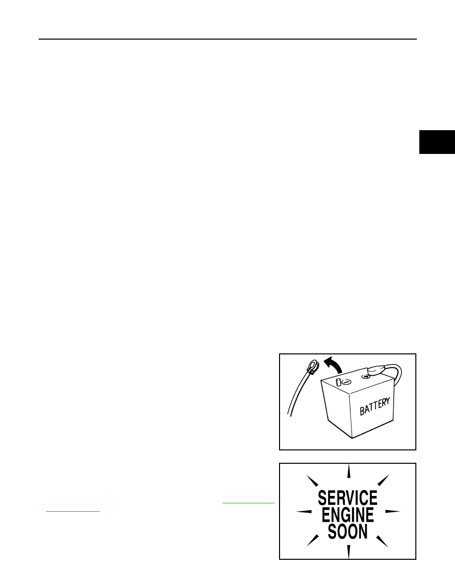
• Turn ignition switch OFF and disconnect the battery cable
from the negative terminal before connecting or disconnect-
ing the A/T assembly harness connector. Because battery
voltage is applied to TCM even if ignition switch is turned
OFF.
• Perform “DTC (Diagnostic Trouble Code) CONFIRMATION
PROCEDURE” after performing each TROUBLE DIAGNOSIS.
If the repair is completed DTC should not be displayed in the
“DTC CONFIRMATION PROCEDURE”.
• Always use the specified brand of ATF. Refer to
.
• Use lint-free paper not cloth rags during work.
• Dispose of the waste oil using the methods prescribed by law, ordi-
nance, etc. after replacing the ATF.
• Before proceeding with disassembly, thoroughly clean the outside
of the transmission. It is important to prevent the internal parts from
becoming contaminated by dirt or other foreign matter.
SEF289H
SEF217U
TM-158
< PRECAUTION >
[7AT: RE7R01A (VQ35HR)]
PRECAUTIONS
• Disassembly should be done in a clean work area.
• Use lint-free paper or towels for wiping parts clean. Common shop rags can leave fibers that could interfere
with the operation of the transmission.
• Place disassembled parts in order for easier and proper assembly.
• All parts should be carefully cleaned with a general purpose, non-flammable solvent before inspection or
reassembly.
• Gaskets, seals and O-rings should be replaced any time the A/T is disassembled.
• It is very important to perform functional tests whenever they are indicated.
• The valve body contains precision parts and requires extreme care when parts are removed and serviced.
Place disassembled valve body parts in order for easier and proper assembly. Care will also prevent springs
and small parts from becoming scattered or lost.
• Properly installed valves, sleeves, plugs, etc. will slide along bores in valve body under their own weight.
• Before assembly, apply a coat of recommended ATF to all parts. Apply petroleum jelly to protect O-rings and
seals, or hold bearings and washers in place during assembly. Never use grease.
• Extreme care should be taken to avoid damage to O-rings, seals and gaskets when assembling.
• Clean or replace ATF cooler if excessive foreign material is found in oil pan or clogging strainer. Refer to
158, "Service Notice or Precaution"
• When the A/T drain plug is removed, only some of the ATF is drained. Old ATF will remain in torque con-
verter and ATF cooling system.
Always follow the procedures under “Changing” when changing ATF. Refer to
.
• Occasionally, the parking gear may be locked with the torque insufficiently released, when stopping the vehi-
cle by shifting the selector lever from “D” or “R” to “P” position with the brake pedal depressed.
In this case, the shock with a thud caused by the abrupt release of torque may occur when shifting the selec-
tor lever from “P” position to other positions.
However, this symptom is not a malfunction which results in the damage of parts.
Service Notice or Precaution
INFOID:0000000005250143
ATF COOLER SERVICE
If ATF contains frictional material (clutches, bands, etc.), or if an A/T is repaired, overhauled, or replaced,
inspect and clean the A/T fluid cooler mounted in the radiator or replace the radiator. Flush cooler lines using
cleaning solvent and compressed air after repair. For A/T fluid cooler cleaning procedure, refer to
. For radiator replacement, refer to
.
Нет комментариевНе стесняйтесь поделиться с нами вашим ценным мнением.
Текст