Infiniti FX35, FX50 (S51). Manual — part 288
BRM-30
< REMOVAL AND INSTALLATION >
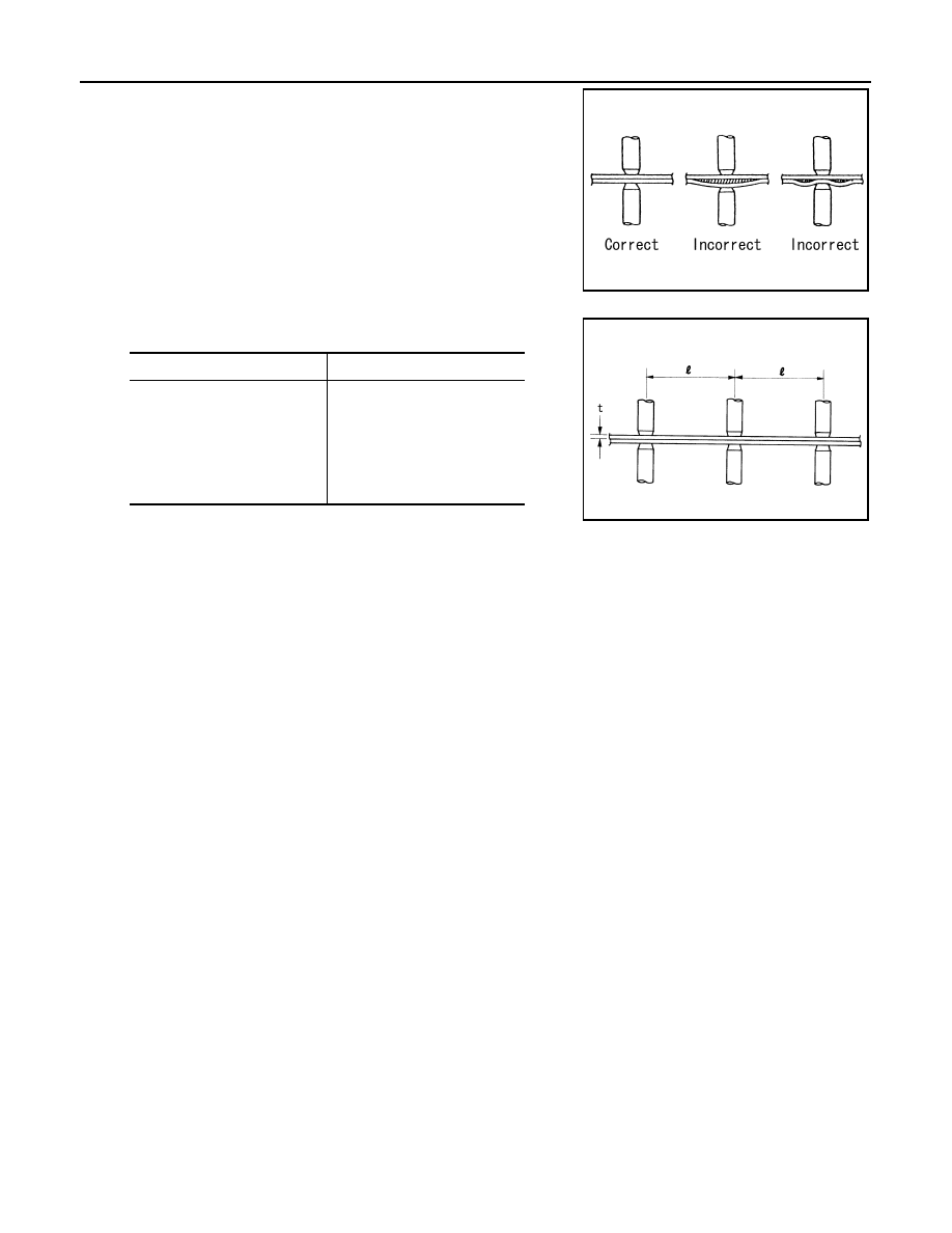
REPAIRING HIGH STRENGTH STEEL
• The panel surfaces must fit flush to each other, leaving no
gaps.
• Follow the specifications for the proper welding pitch.
Unit: mm (in)
PIIA0147E
Thickness (t)
Minimum pitch (l)
0.6 (0.024)
0.8 (0.031)
1.0 (0.039)
1.2 (0.047)
1.6 (0.063)
1.8 (0.071)
10 (0.39) or over
12 (0.47) or over
18 (0.71) or over
20 (0.79) or over
27 (1.06) or over
31 (1.22) or over
PIIA0148E
REPLACEMENT OPERATIONS
BRM-31
< REMOVAL AND INSTALLATION >
C
D
E
F
G
H
I
J
L
M
A
B
BRM
N
O
P
REPLACEMENT OPERATIONS
Description
INFOID:0000000005248959
• This section is prepared for technicians who have attained a high level of skill and experience in repairing
collision-damaged vehicles and also use modern service tools and equipment. Persons unfamiliar with body
repair techniques should not attempt to repair collision-damaged vehicles by using this section.
• Technicians are also encouraged to read Body Repair Manual (Fundamentals) in order to ensure that the
original functions and quality of the vehicle can be maintained. The Body Repair Manual (Fundamentals)
contains additional information, including cautions and warning, that are not including in this manual. Techni-
cians should refer to both manuals to ensure proper repairs.
• Please note that these information are prepared for worldwide usage, and as such, certain procedures might
not apply in some regions or countries.
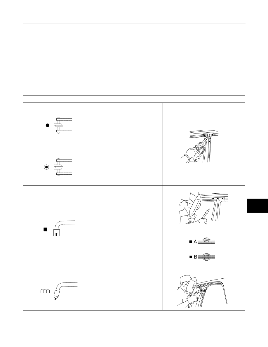
The symbols used in this section for welding operations are shown below.
Symbol marks
Description
2-spot welds
3-spot welds
MIG plug weld
For 3 panels plug weld method
MIG seam weld / Point weld
JSKIA0049ZZ
JSKIA0053ZZ
JSKIA0050ZZ
JSKIA0051ZZ
JSKIA0054ZZ
JSKIA0055ZZ
JSKIA0052ZZ
JSKIA0056ZZ
BRM-32
< REMOVAL AND INSTALLATION >
REPLACEMENT OPERATIONS
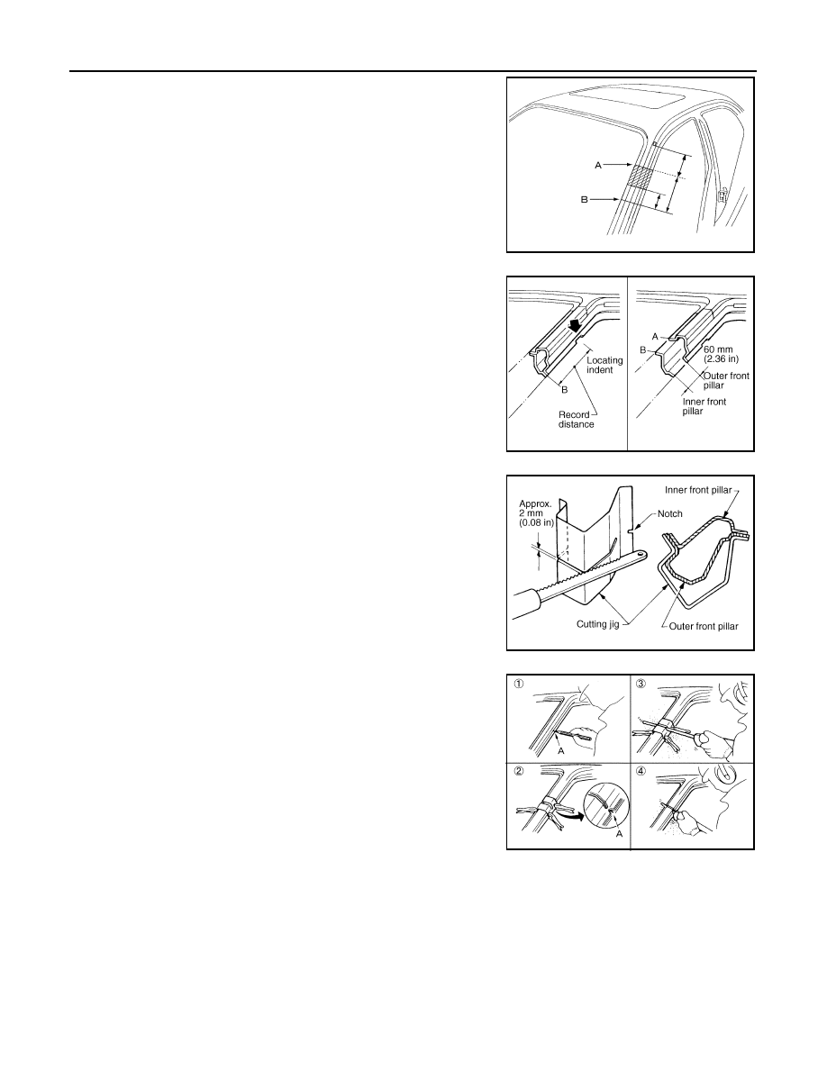
• Front pillar butt joint can be determined anywhere within shaded
area as shown in the figure. The best location for the butt joint is at
position A due to the construction of the vehicle. Refer to the front
pillar section.
• Determine cutting position and record distance from the locating
indent. Use this distance when cutting the service part. Cut outer
front pillar over 60 mm (2.36 in) above inner front pillar cut position.
• Prepare a cutting jig to make outer pillar easier to cut. Also, this will
permit service part to be accurately cut at joint position.
• An example of cutting operation using a cutting jig is as follows.
1.
Mark cutting lines.
A: Cut position of outer pillar
B: Cut position of inner pillar
2.
Align cutting line with notch on jig. Clamp jig to pillar.
3.
Cut outer pillar along groove of jig (at position A).
4.
Remove jig and cut remaining portions.
5.
Cut inner pillar at position B in same manner.
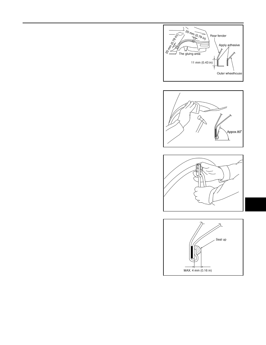
REAR FENDER HEMMING PROCESS
1.
A wheel arch is to be installed and hemmed over left and right outer wheel house.
2.
In order to hem the wheel arch, it is necessary to repair any damaged or defaced parts around outer
wheel house.
CAUTION:
Ensure that the area that is to be glued around outer wheelhouse is undamaged or defaced.
Procedure of the hemming process
PIIA0150E
JSKIA0104GB
JSKIA0105GB
PIIA0153E
REPLACEMENT OPERATIONS
BRM-33
< REMOVAL AND INSTALLATION >
C
D
E
F
G
H
I
J
L
M
A
B
BRM
N
O
P
• Peel off old bonding material on the surface of outer wheelhouse
and clean thoroughly.
• Peel off a primer coat in the specified area where new adhesive is
to be applied on rear fender (the replacing part).
• Apply new adhesive to both specified areas of outer wheelhouse
and rear fender.
• Attach rear fender to the body of the car, and weld the required
part except the hemming part.
• Bend the welded part starting from the center of the wheel arch
gradually with a hammer and a dolly. (Also hem the end of the
flange.)
• Hemming with a hammer is conducted to an approximate angle of
80 degrees.
• Starting from the center, hem the wheel arch gradually, using slight
back and forth motion with a hemming tool.
• Seal up the area around the hemmed end of the flange.
FOAM REPAIR
During factory body assembly, foam insulators are installed in certain body panels and locations around the
vehicle. Use the following procedure (s) to replace any factory-installed foam insulators.
Urethane foam applications
Use commercially available spray foam for sealant (foam material) repair of material used on vehicle. Read
instructions on product for fill procedures.
1.
Fill procedures after installation of service part.
-
Remove foam material remaining on vehicle side.
-
Clean area in which foam was removed.
-
Install service part.
<Adhesive>
3M automix panel bond 8115,
or any equivalents
JSKIA0136GB
SIIA2245E
SIIA2246E
JSKIA0137GB
Нет комментариевНе стесняйтесь поделиться с нами вашим ценным мнением.
Текст