Infiniti FX35, FX50 (S51). Manual — part 254
DIAGNOSIS SYSTEM [ABS ACTUATOR AND ELECTRIC UNIT (CONTROL
UNIT)]
BRC-47
< SYSTEM DESCRIPTION >
[VDC/TCS/ABS]
C
D
E
G
H
I
J
K
L
M
A
B
BRC
N
O
P
NOTE:
1: A brief moment of On/Off condition occurs every 20 seconds after ignition switch turned ON. This is not malfunction because it is an
operation for checking.
2: With LDP models.
ACTIVE TEST
CAUTION:
• Never perform active test while driving vehicle.
• Make sure to completely bleed air from brake system.
• The active test cannot be started when ABS warning lamp, VDC OFF indicator lamp, SLIP indicator
lamp and brake warning lamp are ON.
• ABS warning lamp, VDC OFF indicator lamp, SLIP indicator lamp and brake warning lamp are ON
during active test.
• Erase memory of the lane camera unit after implementing active test. Refer to
NOTE:
• When active test is performed while depressing the pedal, the pedal depression amount will change. This is
normal. (Only solenoid valve and ABS motor.)
• “TEST IS STOPPED” in “ABS” with CONSULT-III is displayed 10 seconds after operation start.
• After “TEST IS STOPPED” in “ABS” with CONSULT-III is displayed, to perform test again.
Test Item
ABS SOLENOID VALVE
• Select “Up”, “Keep” and “Down” of “ACTIVE TEST” in “ABS” with CONSULT-III. Then use screen monitor to
check that solenoid valve operates as shown in the table below.
LDP) LDW SW
(On/Off) (Note 2)
×
×
LDW switch status received from lane camera unit via
CAN communication
LDP) SHIFT POSITION
(OFF/P/R/N/D/MM 1st – MM 7th)
(Note 2)
×
×
Shift position received from TCM via CAN communication
LDP) TURN SIGNAL
(Off/LH/RH/LH&RH) (Note 2)
×
×
Turn signal operating condition received from BCM via
CAN communication
Monitor item (Unit)
SELECT MONITOR ITEM
Remarks
ECU INPUT
SIGNALS
MAIN SIGNALS
Test item
Display item
Display (Note)
Up
Keep
Down
FR RH SOL
FR RH IN SOL
Off
On
On
FR RH OUT SOL
Off
Off
On*
USV[FR-RL]
Off
Off
Off
HSV[FR-RL]
Off
Off
Off
FR LH SOL
FR LH IN SOL
Off
On
On
FR LH OUT SOL
Off
Off
On*
USV[FL-RR]
Off
Off
Off
HSV[FL-RR]
Off
Off
Off
RR RH SOL
RR RH IN SOL
Off
On
On
RR RH OUT SOL
Off
Off
On*
USV[FL-RR]
Off
Off
Off
HSV[FL-RR]
Off
Off
Off

BRC-48
< SYSTEM DESCRIPTION >
[VDC/TCS/ABS]
DIAGNOSIS SYSTEM [ABS ACTUATOR AND ELECTRIC UNIT (CONTROL
UNIT)]
*: On for 1 to 2 seconds after the select, and then Off.
NOTE:
A brief moment of On/Off condition occurs every 20 seconds after ignition switch turned ON. This is not malfunction because it is an
operation for checking.
ABS SOLENOID VALVE (ACT)
• Select “Up”, “ACT UP” and “ACT KEEP” of “ACTIVE TEST” in “ABS” with CONSULT-III. Then use screen
monitor to check that solenoid valve operates as shown in the table below.
*: On for 1 to 2 seconds after the select, and then Off.
NOTE:
A brief moment of On/Off condition occurs every 20 seconds after ignition switch turned ON. This is not malfunction because it is an
operation for checking.
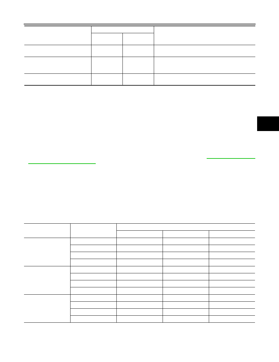
ABS MOTOR
• Select “On” and “Off” of “ACTIVE TEST” in “ABS” with CONSULT-III. Make sure motor relay and actuator
relay operates as shown in table below.
NOTE:
A brief moment of On/Off condition occurs every 20 seconds after ignition switch turned ON. This is not malfunction because it is an
operation for checking.
ECU IDENTIFICATION
RR LH SOL
RR LH IN SOL
Off
On
On
RR LH OUT SOL
Off
Off
On*
USV[FR-RL]
Off
Off
Off
HSV[FR-RL]
Off
Off
Off
Test item
Display item
Display (Note)
Up
Keep
Down
Test item
Display item
Display (Note)
Up
ACT UP
ACT KEEP
FR RH ABS SOLENOID
(ACT)
FR RH IN SOL
Off
Off
Off
FR RH OUT SOL
Off
Off
Off
USV[FR-RL]
Off
On
On
HSV[FR-RL]
Off
On*
Off
FR LH ABS SOLENOID
(ACT)
FR LH IN SOL
Off
Off
Off
FR LH OUT SOL
Off
Off
Off
USV[FL-RR]
Off
On
On
HSV[FL-RR]
Off
On*
Off
RR RH ABS SOLENOID
(ACT)
RR RH IN SOL
Off
Off
Off
RR RH OUT SOL
Off
Off
Off
USV[FL-RR]
Off
On
On
HSV[FL-RR]
Off
On*
Off
RR LH ABS SOLENOID
(ACT)
RR LH IN SOL
Off
Off
Off
RR LH OUT SOL
Off
Off
Off
USV[FR-RL]
Off
On
On
HSV[FR-RL]
Off
On*
Off
Test item
Display item
Display
On
Off
ABS MOTOR
MOTOR RELAY
On
Off
ACTUATOR RLY (Note)
On
On

DIAGNOSIS SYSTEM [ABS ACTUATOR AND ELECTRIC UNIT (CONTROL
UNIT)]
BRC-49
< SYSTEM DESCRIPTION >
[VDC/TCS/ABS]
C
D
E
G
H
I
J
K
L
M
A
B
BRC
N
O
P
ABS actuator and electric unit (control unit) part number can be read.
SPECIFIC FUNCTION
Specific Data Monitor
Specific data monitor displays specific LDP operating conditions.
Monitor item (Unit)
Remarks
YAW RATE SEN
(d/s)
Yaw rate detected by yaw rate/side G sensor
LDP) YAW ORDER
(
×
100Nm)
Calculated target yaw moment
LDP) WARN REQ
(On/Off)
Status of warning request that transmits to lane camera unit via CAN communi-
cation
LDP) WARN control
(On/Off)
Status of warning main controller for LDP
LDP) REDY signal
(On/Off)
Status of internal judgment by LDP controller [ABS actuator and electric unit
(control unit)]
LDP) STATUS signal
(STANDBY/WARN/MASK/Off)
Status of internal judgment by LDP controller [ABS actuator and electric unit
(control unit)]
LDP) Camera lost
(Detect/Deviate/Both)
Lane marker detected condition received from lane camera unit via CAN com-
munication
LDP) Lane unclear
(On/Off)
Lane marker condition received from lane camera unit via CAN communication

BRC-50
< DTC/CIRCUIT DIAGNOSIS >
[VDC/TCS/ABS]
C1101, C1102, C1103, C1104 WHEEL SENSOR
DTC/CIRCUIT DIAGNOSIS
C1101, C1102, C1103, C1104 WHEEL SENSOR
Description
INFOID:0000000005234498
When the sensor rotor rotates, the magnetic field changes. Wheel sensor converts the magnetic field changes
to current signals (rectangular wave) and transmits them to the ABS actuator and electric unit (control unit).
DTC Logic
INFOID:0000000005234499
DTC DETECTION LOGIC
DTC CONFIRMATION PROCEDURE
1.
DTC REPRODUCTION PROCEDURE
1.
Start the engine and drive the vehicle at 30 km/h (19 MPH) or more for approximately 1 minute.
2.
Perform self-diagnosis for “ABS” with CONSULT-III.
Is DTC “C1101”, “C1102”, “C1103” or “C1104” detected?
YES
>> Proceed to diagnosis. Refer to
.
NO
>> INSPECTION END
Diagnosis Procedure
INFOID:0000000005234500
CAUTION:
Never check between wheel sensor terminals.
1.
CHECK TIRES
Check air pressure, wear and size. Refer to
Is the inspection result normal?
YES
>> GO TO 2.
NO
>> Repair or replace error-detected parts.
2.
CHECK SENSOR AND SENSOR ROTOR
• Check sensor rotor for damage.
• Check wheel sensor for damage, disconnection or looseness.
Is the inspection result normal?
YES
>> GO TO 3.
NO
>> Repair wheel sensor mount or replace sensor rotor. Then perform self-diagnosis for "ABS" with
CONSULT-III.
3.
CHECK CONNECTOR
1.
Turn the ignition switch OFF.
2.
Disconnect ABS actuator and electric unit (control unit) harness connector.
3.
Disconnect malfunctioning wheel sensor harness connector.
4.
Check terminal to see if it is deformed, disconnected, looseness, etc.
Is the inspection result normal?
YES
>> GO TO 4.
DTC
Display item
Malfunction detected condition
Possible cause
C1101
RR RH SENSOR-1
Circuit of rear RH wheel sensor is open. Or when the sen-
sor power voltage is outside the standard.
• Harness or connector
• Wheel sensor
• ABS actuator and electric unit
(control unit)
C1102
RR LH SENSOR-1
Circuit of rear LH wheel sensor is open. Or when the sen-
sor power voltage is outside the standard.
C1103
FR RH SENSOR-1
Circuit of front RH wheel sensor is open. Or when the
sensor power voltage is outside the standard.
C1104
FR LH SENSOR-1
Circuit of front LH wheel sensor is open. Or when the
sensor power voltage is outside the standard.
Нет комментариевНе стесняйтесь поделиться с нами вашим ценным мнением.
Текст