Infiniti FX35, FX50 (S51). Manual — part 253
EBD
BRC-43
< SYSTEM DESCRIPTION >
[VDC/TCS/ABS]
C
D
E
G
H
I
J
K
L
M
A
B
BRC
N
O
P
Component Description
INFOID:0000000005234496
7.
Front wheel sensor
8.
Yaw rate/side G sensor
9.
VDC OFF switch
10. Rear wheel sensor
A.
Back of spiral cable assembly
B.
Combination meter
C.
Inside brake master cylinder cover
D.
Steering knuckle
E.
Under center console
F.
Instrument driver lower panel
G.
Rear final drive assembly
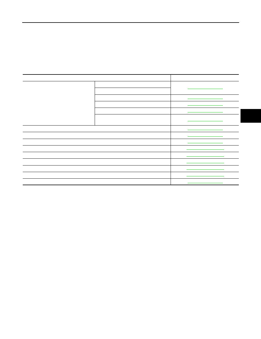
Component parts
Reference
ABS actuator and electric unit (control unit)
Pump
Motor
Actuator relay (main relay)
Solenoid valve
Pressure sensor
VDC switch-over valve
(USV1, USV2, HSV1, HSV2)
Wheel sensor
Yaw rate/side G sensor
Steering angle sensor
VDC OFF switch
ABS warning lamp
Brake warning lamp
VDC OFF indicator lamp
SLIP indicator lamp
Vacuum sensor (Only VK50VE models)

BRC-44
< SYSTEM DESCRIPTION >
[VDC/TCS/ABS]
DIAGNOSIS SYSTEM [ABS ACTUATOR AND ELECTRIC UNIT (CONTROL
UNIT)]
DIAGNOSIS SYSTEM [ABS ACTUATOR AND ELECTRIC UNIT (CONTROL
UNIT)]
CONSULT-III Function
INFOID:0000000005234497
FUNCTION
CONSULT-III can display each diagnostic item using the diagnostic test modes shown following.
WORK SUPPORT
CAUTION:
Erase DTC memory of the lane camera unit after implementing work support. Refer to
SULT-III Function (LANE CAMERA)"
.
SELF DIAGNOSTIC RESULT
Operation Procedure
Before performing the self-diagnosis for “ABS” with CONSULT-III, start engine and drive vehicle at 30 km/h (19
MPH) or more for approximately 1 minute.
Display Item List
How to Erase Self-diagnosis Results
After erasing DTC memory for “ABS” with CONSULT-III, start the engine and drive the vehicle at 30 km/h (19
MPH) or more for approximately 1 minute as the final inspection, and make sure that the ABS warning lamp,
VDC OFF indicator lamp, SLIP indicator lamp and brake warning lamp turn OFF.
CAUTION:
If memory cannot be erased, perform applicable diagnosis.
NOTE:
• When the wheel sensor malfunctions, after inspecting the wheel sensor system, ABS warning lamp, VDC
OFF indicator lamp, SLIP indicator lamp and brake warning lamp will not turn OFF even when the system is
normal unless the vehicle is driven at approximately 30 km/h (19 MPH) or more for approximately 1 minute.
• Brake warning lamp will turn ON in case of parking brake operation (when switch is ON) or in case of brake
fluid level switch operation (when brake fluid is insufficient).
• VDC OFF switch should not stay in “ON” position.
DATA MONITOR
Display Item List
Diagnostic test mode
Function
Work support
This mode enables a technician to adjust some devices faster and more accurately by following
the indications on CONSULT-III.
Self diagnostic result
Self-diagnostic results can be read and erased quickly.
Data monitor
Input/Output data in the ABS actuator and electric unit (control unit) can be read.
Active test
CONSULT-III drives some actuators apart from ABS actuator and electric unit (control unit) and
also shifts some parameters in a specified range.
ECU identification
ABS actuator and electric unit (control unit) part number can be read.
Special Function
Specific LDP data in the ABS actuator and electric unit (control unit) can be read.
Item
Description
ST ANGLE SENSOR ADJUSTMENT
Adjusts the neutral position of the steering angle sensor.
DIAGNOSIS SYSTEM [ABS ACTUATOR AND ELECTRIC UNIT (CONTROL
UNIT)]
BRC-45
< SYSTEM DESCRIPTION >
[VDC/TCS/ABS]
C
D
E
G
H
I
J
K
L
M
A
B
BRC
N
O
P
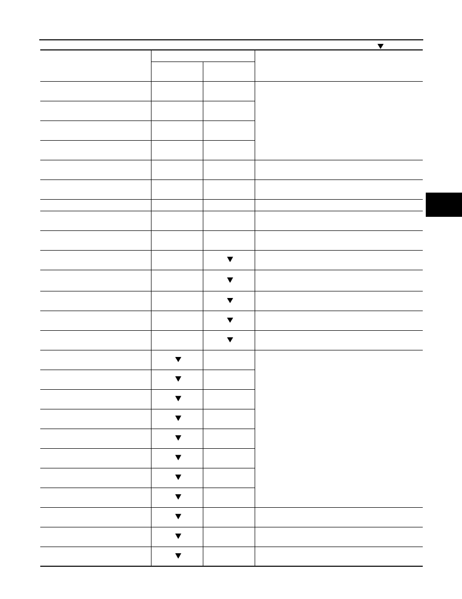
×
: Applicable
: Optional item
Monitor item (Unit)
SELECT MONITOR ITEM
Remarks
ECU INPUT
SIGNALS
MAIN SIGNALS
FR LH SENSOR
[km/h (MPH)]
×
×
Wheel speed
FR RH SENSOR
[km/h (MPH)]
×
×
RR LH SENSOR
[km/h (MPH)]
×
×
RR RH SENSOR
[km/h (MPH)]
×
×
STOP LAMP SW
(On/Off)
×
×
Stop lamp switch signal status
BATTERY VOLT
(V)
×
×
Battery voltage supplied to the ABS actuator and electric
unit (control unit)
SLCT LVR POSI
×
×
A/T selector lever position
YAW RATE SEN
(d/s)
×
×
Yaw rate detected by yaw rate/side G sensor
OFF SW
(On/Off)
×
×
VDC OFF switch signal status
ACCEL POS SIG
(%)
×
Throttle actuator opening/closing is displayed (Linked with
accelerator pedal)
SIDE G-SENSOR
(m/s
2
)
×
Transverse G detected by yaw rate/side G sensor
STR ANGLE SIG
(
°
)
×
Steering angle detected by steering angle sensor
PRESS SENSOR
(bar)
×
Brake fluid pressure detected by pressure sensor
ENGINE RPM
[tr/min (rpm)]
×
Engine speed
FR RH IN SOL
(On/Off) (Note 1)
×
Operation status of each solenoid valve
FR RH OUT SOL
(On/Off) (Note 1)
×
FR LH IN SOL
(On/Off) (Note 1)
×
FR LH OUT SOL
(On/Off) (Note 1)
×
RR RH IN SOL
(On/Off) (Note 1)
×
RR RH OUT SOL
(On/Off) (Note 1)
×
RR LH IN SOL
(On/Off) (Note 1)
×
RR LH OUT SOL
(On/Off) (Note 1)
×
MOTOR RELAY
(On/Off)
×
Motor and motor relay operation
ACTUATOR RLY
(On/Off) (Note 1)
×
Actuator relay operation
ABS WARN LAMP
(On/Off)
×
ABS warning lamp

BRC-46
< SYSTEM DESCRIPTION >
[VDC/TCS/ABS]
DIAGNOSIS SYSTEM [ABS ACTUATOR AND ELECTRIC UNIT (CONTROL
UNIT)]
OFF LAMP
(On/Off)
×
VDC OFF indicator lamp
SLIP LAMP
(On/Off)
×
SLIP indicator lamp
FLUID LEV SW
(On/Off)
Brake fluid level switch signal status
PARK BRAKE SW
(On/Off)
Parking brake switch signal status
EBD SIGNAL
(On/Off)
EBD operation
ABS SIGNAL
(On/Off)
ABS operation
TCS SIGNAL
(On/Off)
TCS operation
VDC SIGNAL
(On/Off)
VDC operation
ABS FAIL SIG
(On/Off)
ABS fail-safe signal
TCS FAIL SIG
(On/Off)
TCS fail-safe signal
VDC FAIL SIG
(On/Off)
VDC fail-safe signal
CRANKING SIG
(On/Off)
Crank operation
USV[FR-RL]
(On/Off) (Note 1)
VDC switch-over valve
USV[FL-RR]
(On/Off) (Note 1)
HSV[FR-RL]
(On/Off) (Note 1)
HSV[FL-RR]
(On/Off) (Note 1)
BST OPER SIG
(On/Off)
Booster operation signal
V/R OUTPUT
(On/Off)
Solenoid valve relay activated
M/R OUTPUT
(On/Off)
Actuator motor and motor relay activated
LDP) APP SEN
(%) (Note 2)
×
×
Accelerator pedal position sensor status received from
ECM via CAN communication
LDP) ICC MAIN SW
(On/Off) (Note 2)
×
×
ICC main switch status received from ECM via CAN com-
munication
LDP) LDP ON SW
(On/Off) (Note 2)
×
×
LDP switch status received from ECM via CAN communi-
cation
LDP) WIPER SIGNAL
(Stop/PRTCT/1low/1high/Low/High)
(Note 2)
×
×
Front wiper operating condition received from BCM via
CAN communication
LDP) BRAKE SW
(On/Off) (Note 2)
×
×
Brake switch signal status
LDP) STOP LMP SW
(On/Off) (Note 2)
×
×
Stop lamp switch signal status
Monitor item (Unit)
SELECT MONITOR ITEM
Remarks
ECU INPUT
SIGNALS
MAIN SIGNALS
Нет комментариевНе стесняйтесь поделиться с нами вашим ценным мнением.
Текст