Infiniti FX35, FX50 (S51). Manual — part 1761
ST-36
< REMOVAL AND INSTALLATION >
POWER STEERING OIL PUMP
POWER STEERING OIL PUMP
VQ35HR
VQ35HR : Exploded View
INFOID:0000000005235286
REMOVAL
DISASSEMBLY
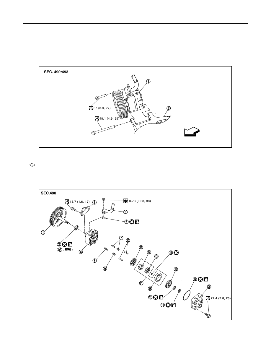
1.
Power steering oil pump
2.
Bracket
: Vehicle front
Refer to
for symbols in the figure.
JSGIA0046GB
1.
Pulley
2.
Oil seal
3.
Bracket
4.
Body assembly
5.
Suction pipe
6.
O-ring
JSGIA0364GB
POWER STEERING OIL PUMP
ST-37
< REMOVAL AND INSTALLATION >
C
D
E
F
H
I
J
K
L
M
A
B
ST
N
O
P
VQ35HR : Removal and Installation
INFOID:0000000005235287
REMOVAL
1.
Drain power steering fluid from reservoir tank.
2.
Remove the right of the air cleaner and air duct. Refer to
EM-17, "Removal and Installation"
3.
Loosen drive belt. Refer to
.
4.
Remove drive belt from oil pump pulley.
5.
Remove pressure sensor connector.
6.
Remove copper washers and eye bolt (drain fluid from their pipings).
7.
Remove suction hose (drain fluid from their pipings).
8.
Remove oil pump mounting bolts, and then remove oil pump.
INSTALLATION
Note the following, and install in the reverse order of removal.
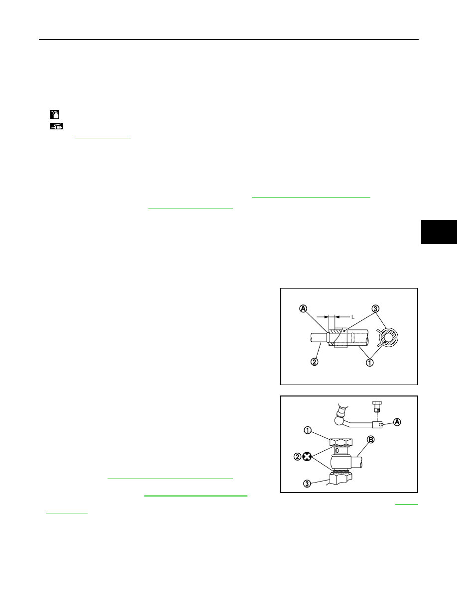
• When installing suction hoses (1), refer to the figure.
CAUTION:
• Never apply fluid to the hose (1) and tube (2).
• Insert hose securely until it contacts spool (A) of tube.
• Leave clearance (L) when installing clamp (3).
• When installing eye bolt (1) and copper washer (2) to oil pump (3),
refer to the figure.
CAUTION:
• Never reuse copper washer.
• Apply power steering fluid to around copper washers, then
install eye bolt.
• Install eye bolt with eye joint (assembled to high pressure
hose) (B) protrusion (A) facing with pump side cutout, and
then tighten it to the specified torque after tightening by
hand. Refer to
ST-48, "VQ35HR : Exploded View"
.
• Securely insert harness connector to pressure sensor.
• Adjust belt tension. Refer to
• Check fluid level, fluid leakage and air bleeding hydraulic system after the installation. Refer to
VQ35HR : Disassembly and Assembly
INFOID:0000000005235288
DISASSEMBLY
1.
Remove rear cover mounting bolts, and then remove rear cover from body assembly.
CAUTION:
7.
Flow control valve B assembly
8.
Flow control valve spring
9.
Flow control valve A
10. Dowel pin
11.
Front side plate
12. Vane
13. Rotor
14. Rotor snap ring
15. Cam ring
16. Rear side plate
17. O-ring
18. Teflon ring
19. O-ring
20. Rear cover
21. Cartridge
A.
Oil seal lip
: Apply power steering fluid.
: Apply multi-purpose grease.
Refer to
for symbols not described on the above.
Standard
L
: 3 – 8 mm (0.12 – 0.31 in)
JSGIA0118ZZ
JSGIA0452ZZ
ST-38
< REMOVAL AND INSTALLATION >
POWER STEERING OIL PUMP
• Fix oil pump with a vise if necessary.
• Use copper plates when fixing with a vise.
2.
Remove O-ring from body assembly.
3.
Remove rear side plate from cartridge, and then remove Teflon ring and O-ring from rear side plate.
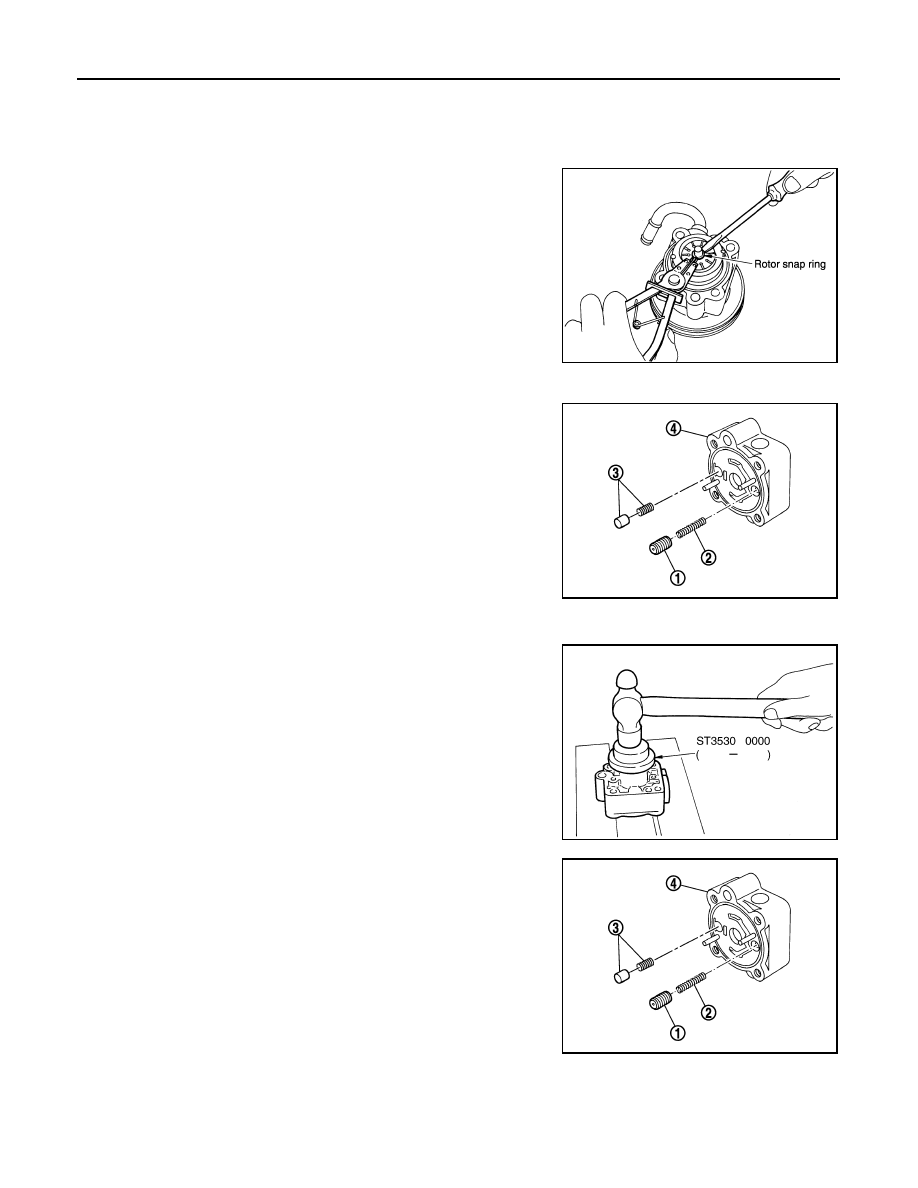
4.
Remove rotor snap ring using a snap ring pliers, and remove
pulley from body assembly.
CAUTION:
Remove pulley so as not to be damaged when removing
rotor snap ring.
5.
Remove cartridge and front side plate.
6.
Remove flow control valve A (1), flow control valve spring (2)
and flow control valve B assembly (3) from body assembly (4).
CAUTION:
Never drop and damage flow control valve A and flow con-
trol valve B assembly when removing.
7.
Remove oil seal from body assembly.
8.
Remove mounting bolt of suction pipe, and then remove suction
pipe from body assembly.
9.
Remove O-ring from body assembly.
10. Remove bracket mounting bolts, and then remove bracket from
body assembly.
ASSEMBLY
1.
Apply recommended grease to oil seal lips. Apply recommended
fluid to around oil seal, and then install oil seal to body assembly
using a drift [SST: ST35300000 (
—
)]
CAUTION:
• Fix oil pump with a vise if necessary.
• Use copper plates when fixing with a vise.
2.
Install bracket to body assembly.
3.
If dowel pin has been removed, insert it into body assembly by
hand. If it cannot be inserted by hand, lightly tap with a hammer.
4.
Install flow control valve A (1), flow control valve spring (2) and
flow control valve B assembly (3) to body assembly (4).
SGIA0059E
JSGIA0365ZZ
SGIA0527E
JSGIA0365ZZ
POWER STEERING OIL PUMP
ST-39
< REMOVAL AND INSTALLATION >
C
D
E
F
H
I
J
K
L
M
A
B
ST
N
O
P
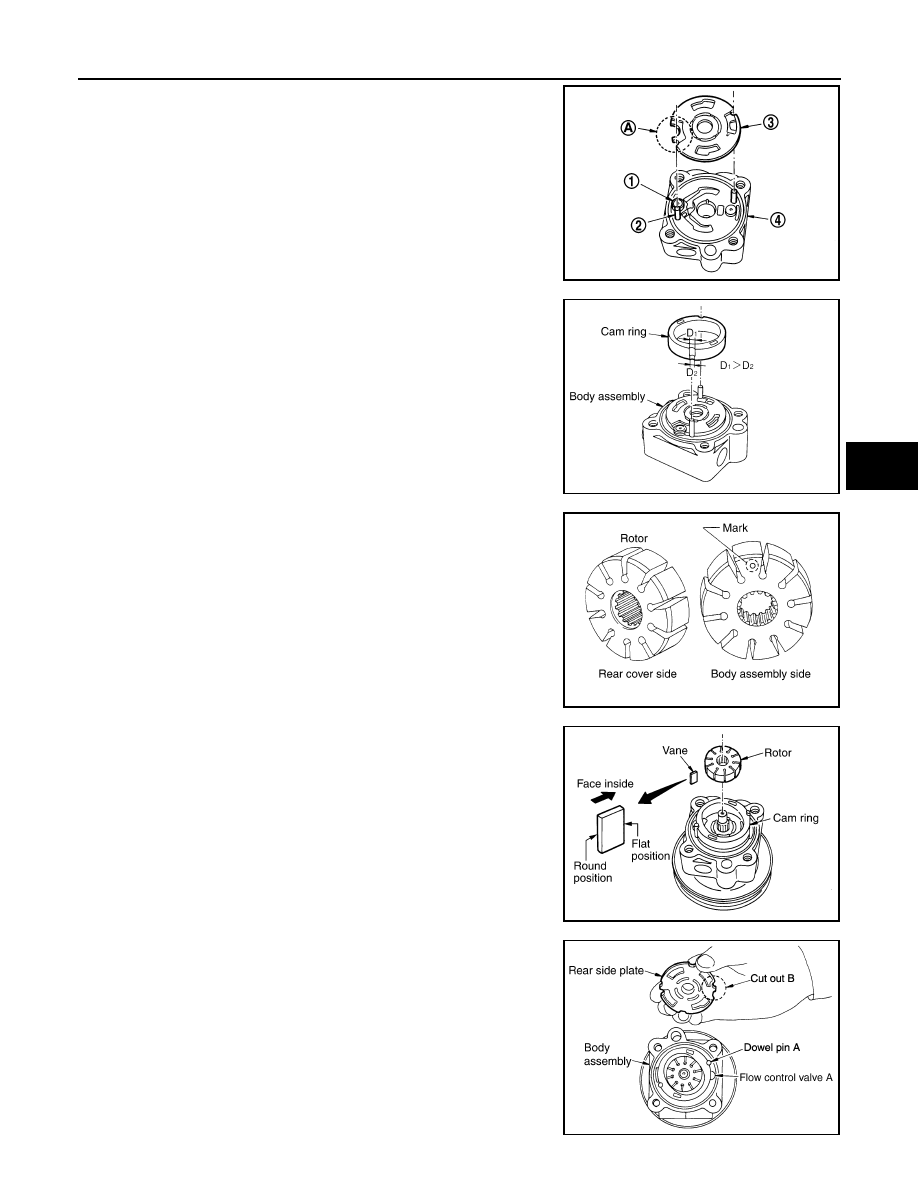
5.
Install front side plate (3) with dowel pin (2) on flow control valve
A (1) side as shown in the figure aligning with front side plate
cutout (A) to body assembly (4).
6.
Install cam ring as shown in the figure.
7.
Install pulley to body assembly.
CAUTION:
Never damage oil seal when installing pulley.
8.
Install rotor so that mark faces body assembly, and then install it
to pulley shaft.
9.
Install vane to rotor so that arc of vane faces cam ring side.
10. Install rotor snap ring to slit of pulley shaft using a hammer and a
drift (commercial service tool).
CAUTION:
• Never damage rotor and pulley shaft.
• Oil pump assembly must be replaced if rotor is damaged.
11. Install rear side plate with dowel pin A on flow control valve A
side as shown in the figure aligning with rear side plate cutout B
to cartridge.
12. Apply recommended fluid to O-ring, and then install O-ring to
body assembly.
13. Apply recommended fluid to O-ring, and then install O-ring to
rear side plate.
14. Apply recommended fluid to Teflon ring, and then install Teflon
ring to rear side plate.
15. Install rear cover to body assembly.
SGIA1189E
SGIA0612E
SGIA0989E
SGIA0613E
PGIA0035E
Нет комментариевНе стесняйтесь поделиться с нами вашим ценным мнением.
Текст