Infiniti FX35, FX50 (S51). Manual — part 315

CCS-80
< DTC/CIRCUIT DIAGNOSIS >
[ICC (FULL SPEED RANGE)]
C1A12 LASER BEAM OFF CENTER
C1A12 LASER BEAM OFF CENTER
Description
INFOID:0000000005501619
ICC sensor integrated unit detects the reflected light from the vehicle ahead by irradiating a laser forward. It
calculates the distance from and relative speed with the vehicle ahead based on the detected signal.
DTC Logic
INFOID:0000000005501620
DTC DETECTION LOGIC
Diagnosis Procedure
INFOID:0000000005501621
1.
ADJUST LASER BEAM AIMING
1.
Adjust the laser beam aiming with CONSULT-III. Refer to
CCS-13, "LASER BEAM AIMING ADJUST-
2.
Perform “All DTC Reading”.
3.
Check if the “C1A12” is detected in “Self Diagnostic Result” of “ICC”.
Is “C1A12” detected?
YES
>> Replace ICC sensor integrated unit. Refer to
NO
>> INSPECTION END
Special Repair Requirement
INFOID:0000000005501622
DESCRIPTION
Perform the action test after adjusting the laser beam aiming of ICC sensor integrated unit when the following
operation is performed.
• Removal and installation of ICC sensor integrated unit
• Replacement of ICC sensor integrated unit
SPECIAL REPAIR REQUIREMENT
1.
LASER BEAM AIMING ADJUSTMENT OF ICC SENSOR INTEGRATED UNIT
Adjust the laser beam aiming of the ICC sensor integrated unit. Refer to
>> GO TO 2.
2.
CHECK ICC SYSTEM
1.
Erase the “Self Diagnostic Result”, and then perform “All DTC Reading” again after performing the action
test. (Refer to
CCS-18, "ACTION TEST : Description"
2.
Check that the ICC system is normal.
>> WORK END
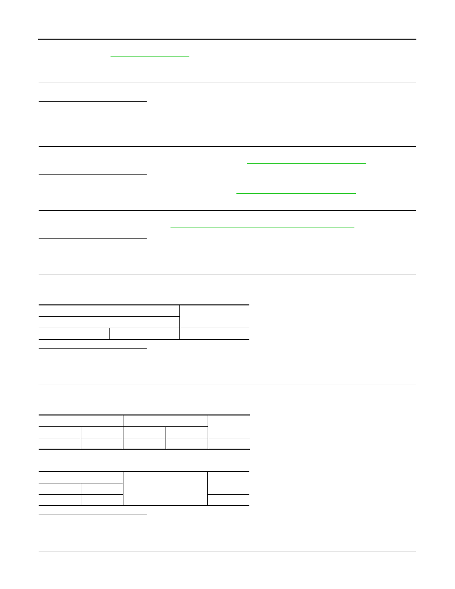
DTC
(On board dis-
play)
Trouble diagnosis name
DTC detecting condition
Possible causes
C1A12
(12)
LASER BEAM OFFCNTR
Laser beam of ICC sensor integrated unit is
off the aiming point
Laser beam is off the aiming point

CCS
C1A13 STOP LAMP RELAY
CCS-81
< DTC/CIRCUIT DIAGNOSIS >
[ICC (FULL SPEED RANGE)]
C
D
E
F
G
H
I
J
K
L
M
B
N
P
A
C1A13 STOP LAMP RELAY
Description
INFOID:0000000005501623
• The ICC sensor integrated unit transmits the ICC brake hold relay drive signal to the brake booster control
unit via ITS communication.
• The ICC brake hold relay activates the stop lamp by the ICC brake hold relay drive signal (stop lamp drive
signal) outputted by the brake booster control unit.
DTC Logic
INFOID:0000000005501624
DTC DETECTION LOGIC
NOTE:
If DTC “C1A13” is detected along with DTC “U1000”, first diagnose the DTC “U1000”. Refer to
.
DTC CONFIRMATION PROCEDURE
1.
PERFORM DTC CONFIRMATION PROCEDURE (1)
1.
Start the engine.
2.
Perform the active test item “STOP LAMP” with CONSULT-III.
3.
Perform “All DTC Reading”.
4.
Check if the “C1A13” is detected as the current malfunction in the “Self Diagnostic Result” of “ICC”.
Is “C1A13” detected as the current malfunction?
YES
>> Refer to
NO
>> GO TO 2.
2.
PERFORM DTC CONFIRMATION PROCEDURE (2)
1.
Drive at the vehicle speed of 40 km/h (25 MPH) or more for approximately 20 seconds or more without the
brake pedal depressed.
CAUTION:
Always drive safely.
NOTE:
If it is outside the above condition, repeat step 1.
2.
Perform “All DTC Reading”.
3.
Check if the “C1A13” is detected as the current malfunction in the “Self Diagnostic Result” of “ICC”.
Is “C1A13” detected as the current malfunction?
YES
>> Refer to
NO
>> Refer to
GI-36, "Intermittent Incident"
.
Diagnosis Procedure
INFOID:0000000005501625
1.
CHECK SELF-DIAGNOSIS RESULTS
Check if “U1000” is detected other than “C1A13” in “Self Diagnostic Result” of “ICC”.
Is “U1000” detected?
DTC
(On board dis-
play)
Trouble diagnosis name
DTC detecting condition
Possible causes
C1A13
(13)
STOP LAMP RLY FIX
• If the stop lamp is not activated even
though the ICC sensor integrated unit is
transmitting a ICC brake hold relay drive
signal.
• If the stop lamp is activated even though
the ICC sensor integrated unit is not trans-
mitting a ICC brake hold relay drive signal.
• Stop lamp switch circuit
• ICC brake switch circuit
• ICC brake hold relay circuit
• Stop lamp switch
• ICC brake switch
• ICC brake hold relay
• Incorrect stop lamp switch installation
• Incorrect ICC brake switch installation
• ECM
CCS-82
< DTC/CIRCUIT DIAGNOSIS >
[ICC (FULL SPEED RANGE)]
C1A13 STOP LAMP RELAY
YES
>> Perform the CAN communication system inspection. Repair or replace the malfunctioning parts.
.
NO
>> GO TO 2.
2.
CHECK STOP LAMP SWITCH AND ICC BRAKE SWITCH
Check that “STOP LAMP SW” and “BRAKE SW” operate normally in “DATA MONITOR” of “ICC”.
Is the inspection result normal?
YES
>> GO TO 12.
NO-1
>> When “BRAKE SW” operation is malfunctioning: GO TO 3.
NO-2
>> When “STOP LAMP SW” operation is malfunctioning: GO TO 9.
3.
CHECK ICC BRAKE SWITCH INSTALLATION
1.
Turn ignition switch OFF.
2.
Check ICC brake switch for correct installation. Refer to
BR-7, "Inspection and Adjustment"
Is the inspection result normal?
YES
>> GO TO 4.
NO
>> Adjust ICC brake switch installation. Refer to
BR-7, "Inspection and Adjustment"
4.
CHECK ICC BRAKE SWITCH
1.
Disconnect ICC brake switch connector.
2.
Check ICC brake switch. Refer to
CCS-64, "Component Inspection (ICC Brake Switch)"
.
Is the inspection result normal?
YES
>> GO TO 5.
NO
>> Replace ICC brake switch.
5.
CHECK ICC BRAKE HOLD RELAY
1.
Remove ICC brake hold relay.
2.
Check for continuity between ICC brake hold relay terminals.
Is the inspection result normal?
YES
>> GO TO 6.
NO
>> Replace ICC brake hold relay.
6.
CHECK HARNESS BETWEEN ICC BRAKE HOLD RELAY AND ICC BRAKE SWITCH
1.
Check for continuity between ICC brake hold relay harness connector and ICC brake switch harness con-
nector.
2.
Check for continuity between ICC brake hold relay harness connector and ground.
Is the inspection result normal?
YES
>> GO TO 7.
NO
>> Repair the harnesses or connectors.
7.
CHECK HARNESS BETWEEN ECM AND ICC BRAKE SWITCH
1.
Disconnect ECM connector.
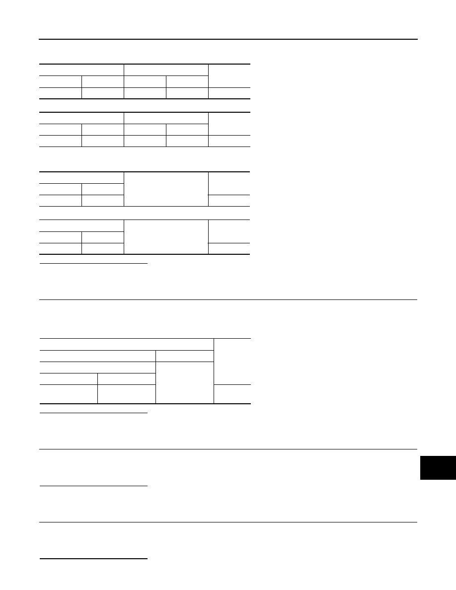
ICC brake hold relay
Continuity
Terminal
3
4
Existed
ICC brake hold relay
ICC brake switch
Continuity
Connector
Terminal
Connector
Terminal
E91
4
E114
1
Existed
ICC brake hold relay
Ground
Continuity
Connector
Terminal
E91
4
Not existed
CCS
C1A13 STOP LAMP RELAY
CCS-83
< DTC/CIRCUIT DIAGNOSIS >
[ICC (FULL SPEED RANGE)]
C
D
E
F
G
H
I
J
K
L
M
B
N
P
A
2.
Check for continuity between the ECM harness connector and ICC brake switch harness connector.
VQ35HR
VK50VE
3.
Check for continuity between ECM harness connector and ground.
VQ35HR
VK50VE
Is the inspection result normal?
YES
>> GO TO 8.
NO
>> Repair the harnesses or connectors.
8.
CHECK ICC BRAKE HOLD RELAY POWER SUPPLY CIRCUIT
1.
Connect ECM connector.
2.
Turn the ignition switch ON.
3.
Check the voltage between ICC brake hold relay harness connector and ground.
Is the inspection result normal?
YES
>> GO TO 20.
NO
>> Repair ICC brake hold relay power supply circuit.
9.
CHECK STOP LAMP FOR ILLUMINATION
1.
Turn the ignition switch OFF.
2.
Remove ICC brake hold relay.
3.
Check that the stop lamp is illuminated by depressing the brake pedal to turn the stop lamp ON.
Is the inspection result normal?
YES
>> GO TO 10.
NO
>> Check the stop lamp circuit, and repair or replace the malfunctioning parts.
10.
CHECK ICC BRAKE HOLD RELAY CIRCUIT
1.
Connect ICC brake hold relay.
2.
Disconnect the stop lamp switch connector.
3.
Check that the stop lamp does not illuminate when brake pedal is not depressed.
Is the inspection result normal?
ECM
ICC brake switch
Continuity
Connector
Terminal
Connector
Terminal
M107
126
E114
2
Existed
ECM
ICC brake switch
Continuity
Connector
Terminal
Connector
Terminal
M160
117
E114
2
Existed
ECM
Ground
Continuity
Connector
Terminal
M107
126
Not existed
ECM
Ground
Continuity
Connector
Terminal
M160
117
Not existed
Terminals
Voltage
(Approx.)
(+)
(–)
ICC brake hold relay
Ground
Connector
Terminal
E91
3
Battery
voltage
Нет комментариевНе стесняйтесь поделиться с нами вашим ценным мнением.
Текст