Infiniti FX35, FX50 (S51). Manual — part 316

CCS-84
< DTC/CIRCUIT DIAGNOSIS >
[ICC (FULL SPEED RANGE)]
C1A13 STOP LAMP RELAY
YES
>> GO TO 20.
NO
>> GO TO 11.
11.
CHECK ICC BRAKE HOLD RELAY
1.
Remove ICC brake hold relay.
2.
Check for continuity between ICC brake hold relay terminals.
Is the inspection result normal?
YES
>> GO TO 20.
NO
>> Replace ICC brake hold relay.
12.
CHECK HARNESS BETWEEN BRAKE BOOSTER CONTROL UNIT AND ICC BRAKE HOLD RELAY
1.
Turn ignition switch OFF.
2.
Disconnect brake booster control unit connector and remove ICC brake hold relay.
3.
Check for continuity between the brake booster control unit harness connector and ICC brake hold relay
harness connector.
4.
Check for continuity between brake booster control unit harness connector and ground.
Is the inspection result normal?
YES
>> GO TO 13.
NO
>> Repair the harnesses or connectors.
13.
CHECK HARNESS BETWEEN ICC BRAKE HOLD RELAY AND GROUND
Check for continuity between ICC brake hold relay harness connector and ground.
Is the inspection result normal?
YES
>> GO TO 14.
NO
>> Repair the harnesses or connectors.
14.
CHECK ICC BRAKE HOLD RELAY
Check resistance between ICC brake hold relay terminals.
Is the inspection result normal?
YES
>> GO TO 15.
NO
>> Replace ICC brake hold relay.
ICC brake hold relay
Continuity
Terminal
7
6
Not existed
Brake booster control unit
ICC brake hold relay
Continuity
Connector
Terminal
Connector
Terminal
B249
47
E91
1
Existed
Brake booster control unit
Ground
Continuity
Connector
Terminal
B249
47
Not existed
ICC brake hold relay
Ground
Continuity
Connector
Terminal
E91
2
Existed
ICC brake hold relay
Resistance
Terminal
1
2
Approx. 75
Ω

CCS
C1A13 STOP LAMP RELAY
CCS-85
< DTC/CIRCUIT DIAGNOSIS >
[ICC (FULL SPEED RANGE)]
C
D
E
F
G
H
I
J
K
L
M
B
N
P
A
15.
CHECK BRAKE BOOSTER CONTROL UNIT OUTPUT VOLTAGE
1.
Connect the brake booster control unit connector.
2.
Turn ignition switch ON.
3.
Perform “STOP LAMP” on “Active Test” of “ICC”, and then check the voltage between ICC brake hold
relay harness connector and ground.
Is the inspection result normal?
YES
>> GO TO 16.
NO
>> GO TO 21.
16.
CHECK ICC BRAKE HOLD RELAY POWER SUPPLY CIRCUIT
1.
Turn ignition switch OFF.
2.
Check the voltage between ICC brake hold relay harness connector and ground.
Is the inspection result normal?
YES
>> GO TO 17.
NO
>> Repair or replace ICC brake hold relay power supply circuit.
17.
CHECK HARNESS BETWEEN ICC BRAKE HOLD RELAY AND ECM
1.
Disconnect ECM, rear combination lamp, and high-mounted stop lamp connectors.
2.
Check for continuity between ICC brake hold relay harness connector and ECM harness connector.
VQ35HR
VK50VE
3.
Check for continuity between ICC brake hold relay harness connector and ground.
Is the inspection result normal?
YES
>> GO TO 18.
Terminal
Condition
Voltage
(Approx.)
(+)
(–)
ICC brake hold relay
Ground
Active Test
item
“STOP LAMP”
Connector
Terminal
E91
1
Off
0 V
On
Battery
voltage
Terminal
Voltage
(Approx.)
(+)
(–)
ICC brake hold relay
Ground
Connector
Terminal
E91
7
Battery
voltage
ICC brake hold relay
ECM
Continuity
Connector
Terminal
Connector
Terminal
E91
6
M107
122
Existed
ICC brake hold relay
ECM
Continuity
Connector
Terminal
Connector
Terminal
E91
6
M160
110
Existed
ICC brake hold relay
Ground
Continuity
Connector
Terminal
E91
6
Not existed

CCS-86
< DTC/CIRCUIT DIAGNOSIS >
[ICC (FULL SPEED RANGE)]
C1A13 STOP LAMP RELAY
NO
>> Repair the harnesses or connectors.
18.
CHECK ICC BRAKE HOLD RELAY
1.
Connect ECM, rear combination lamp, and high-mounted stop lamp connectors and ICC brake hold relay.
2.
Disconnect the stop lamp switch connector.
3.
Turn ignition switch ON.
4.
Perform “STOP LAMP” on “Active Test” of “ICC”, and then check the stop lamp for illumination.
Is the inspection result normal?
YES
>> GO TO 19.
NO
>> Replace ICC brake hold relay.
19.
CHECK ICC BRAKE SWITCH STANDARD VOLTAGE
1.
Turn ignition switch OFF.
2.
Connect the stop lamp switch connector.
3.
Turn ignition switch ON.
4.
Perform “STOP LAMP” on “Active Test” of “ICC”, and then check the voltage between ICC brake switch
harness connector and ground.
Is the inspection result normal?
YES
>> GO TO 20.
NO
>> Replace ICC brake hold relay.
20.
PERFORM SELF-DIAGNOSIS OF ECM
1.
Connect all connectors again if the connectors are disconnected.
2.
Turn ignition switch ON.
3.
Perform “All DTC Reading”.
4.
Check if any DTC is detected in “Self Diagnostic Result” of “ENGINE”. Refer to
(VK50VE).
Is any DTC detected?
YES
>> Repair or replace the malfunctioning parts identified by the self-diagnosis result.
NO
>> GO TO 21.
21.
CHECK ICC BRAKE HOLD RELAY DRIVE SIGNAL OUTPUT
1.
Select the active test item “STOP LAMP” of “ICC”.
2.
Check that “STP LMP DRIVE” is turned ON when operating the test item.
Is the inspection result normal?
YES
>> Replace brake booster control unit.
NO
>> Replace the ICC sensor integrated unit. Refer to
Component Inspection
INFOID:0000000005501626
1.
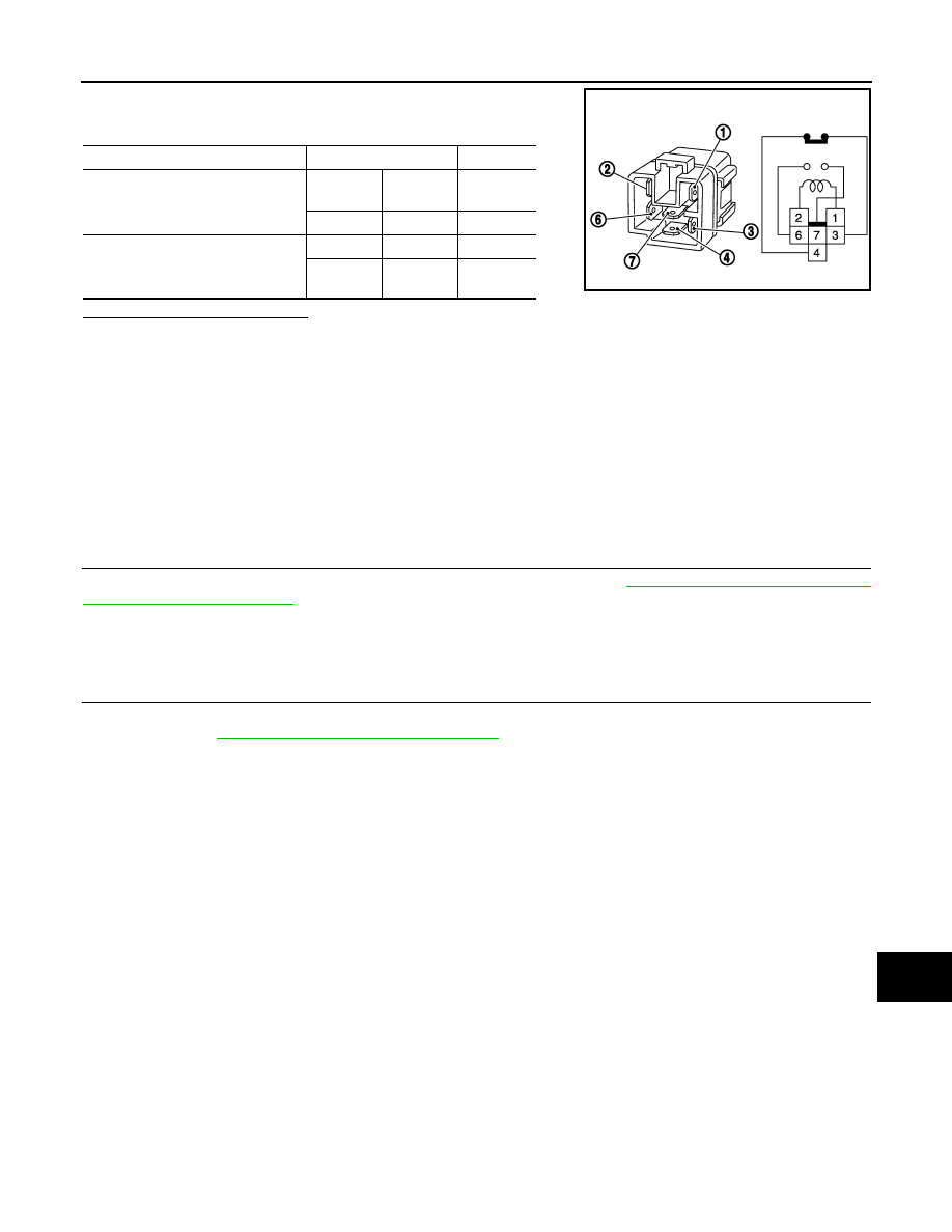
CHECK ICC BRAKE HOLD RELAY
Terminal
Condition
Voltage
(Approx.)
(+)
(–)
ICC brake switch
Ground
Active Test
item
“STOP LAMP”
Connector
Terminal
E114
1
Off
Battery
voltage
On
0 V
CCS
C1A13 STOP LAMP RELAY
CCS-87
< DTC/CIRCUIT DIAGNOSIS >
[ICC (FULL SPEED RANGE)]
C
D
E
F
G
H
I
J
K
L
M
B
N
P
A
Apply battery voltage to ICC brake hold relay terminals 1 and 2, and
then check for continuity under the following conditions.
Is the inspection result normal?
YES
>> INSPECTION END
NO
>> Replace ICC brake hold relay.
Special Repair Requirement
INFOID:0000000005501627
DESCRIPTION
Perform the action test after adjusting the laser beam aiming of ICC sensor integrated unit when the following
operation is performed.
• Removal and installation of ICC sensor integrated unit
• Replacement of ICC sensor integrated unit
SPECIAL REPAIR REQUIREMENT
1.
LASER BEAM AIMING ADJUSTMENT OF ICC SENSOR INTEGRATED UNIT
Adjust the laser beam aiming of the ICC sensor integrated unit. Refer to
>> GO TO 2.
2.
CHECK ICC SYSTEM
1.
Erase the “Self Diagnostic Result”, and then perform “All DTC Reading” again after performing the action
test. (Refer to
CCS-18, "ACTION TEST : Description"
2.
Check that the ICC system is normal.
>> WORK END
Condition
Terminal
Continuity
When the battery voltage is applied
3
4
Not exist-
ed
7
6
Existed
When the battery voltage is not ap-
plied
3
4
Existed
7
6
Not exist-
ed
MBIB0063E
Нет комментариевНе стесняйтесь поделиться с нами вашим ценным мнением.
Текст