Infiniti FX35, FX50 (S51). Manual — part 1177

ECM
HAC-105
< ECU DIAGNOSIS INFORMATION >
[AUTOMATIC AIR CONDITIONER]
C
D
E
F
G
H
J
K
L
M
A
B
HAC
N
O
P
ACCEL SEN 2*
1
• Ignition switch: ON
(Engine stopped)
Accelerator pedal: Fully released
0.45 - 1.0 V
Accelerator pedal: Fully depressed
4.4 - 4.8 V
TP SEN 1-B1
• Ignition switch: ON
(Engine stopped)
• Selector lever: D
Accelerator pedal: Fully released
More than 0.36 V
Accelerator pedal: Fully depressed
Less than 4.75 V
TP SEN 2-B1*
1
• Ignition switch: ON
(Engine stopped)
• Selector lever: D
Accelerator pedal: Fully released
More than 0.36 V
Accelerator pedal: Fully depressed
Less than 4.75 V
FUEL T/TMP SE
• Ignition switch: ON
Indicates fuel tank tempera-
ture
INT/A TEMP SE
• Ignition switch: ON
Indicates intake air temper-
ature
EVAP SYS PRES
• Ignition switch: ON
Approx. 1.8 - 4.8 V
FUEL LEVEL SE
• Ignition switch: ON
Depending on fuel level of
fuel tank
START SIGNAL
• Ignition switch: ON
→
START
→
ON
OFF
→
ON
→
OFF
CLSD THL POS
• Ignition switch: ON
(Engine stopped)
Accelerator pedal: Fully released
ON
Accelerator pedal: Slightly depressed
OFF
AIR COND SIG
• Engine: After warming up, idle the
engine
Air conditioner switch: OFF
OFF
Air conditioner switch: ON
(Compressor operates.)
ON
P/N POSI SW
• Ignition switch: ON
Selector lever: P or N
ON
Selector lever: Except above
OFF
PW/ST SIGNAL
• Engine: After warming up, idle the
engine
Steering wheel: Not being turned
OFF
Steering wheel: Being turned
ON
LOAD SIGNAL
• Ignition switch: ON
Rear window defogger switch: ON
and/or
Lighting switch: 2nd position
ON
Rear window defogger switch and lighting
switch: OFF
OFF
IGNITION SW
• Ignition switch: ON
→
OFF
→
ON
ON
→
OFF
→
ON
HEATER FAN SW
• Engine: After warming up, idle the
engine
Heater fan switch: ON
ON
Heater fan switch: OFF
OFF
BRAKE SW
• Ignition switch: ON
Brake pedal: Fully released
OFF
Brake pedal: Slightly depressed
ON
INJ PULSE-B1
• Engine: After warming up
• Selector lever: P or N
• Air conditioner switch: OFF
• No load
Idle
2.0 - 3.0 msec
2,000 rpm
1.9 - 2.9 msec
INJ PULSE-B2
• Engine: After warming up
• Selector lever: P or N
• Air conditioner switch: OFF
• No load
Idle
2.0 - 3.0 msec
2,000 rpm
1.9 - 2.9 msec
IGN TIMING
• Engine: After warming up
• Selector lever: P or N
• Air conditioner switch: OFF
• No load
Idle
6
°
- 16
°
BTDC (With 4WAS)
10
°
- 20
°
BTDC (Without
4WAS)
2,000 rpm
25
°
- 45
°
BTDC
CAL/LD VALUE
• Engine: After warming up
• Selector lever: P or N
• Air conditioner switch: OFF
• No load
Idle
5% - 35%
2,500 rpm
5% - 35%
Monitor Item
Condition
Values/Status

HAC-106
< ECU DIAGNOSIS INFORMATION >
[AUTOMATIC AIR CONDITIONER]
ECM
MASS AIRFLOW
• Engine: After warming up
• Selector lever: P or N
• Air conditioner switch: OFF
• No load
Idle
2.0 - 6.0 g·m/s
2,500 rpm
7.0 - 20.0 g·m/s
PURG VOL C/V
• Engine: After warming up
• Selector lever: P or N
• Air conditioner switch: OFF
• No load
Idle
(Accelerator pedal: Not depressed even
slightly, after engine starting.)
0%
2,000 rpm
—
INT/V TIM (B1)
• Engine: After warming up
• Selector lever: P or N
• Air conditioner switch: OFF
• No load
Idle
−
5
°
- 5
°
CA
2,000 rpm
Approx. 0
°
- 30
°
CA
INT/V TIM (B2)
• Engine: After warming up
• Selector lever: P or N
• Air conditioner switch: OFF
• No load
Idle
−
5
°
- 5
°
CA
2,000 rpm
Approx. 0
°
- 30
°
CA
EXH/V TIM B1
• Engine: After warming up
• Selector lever: P or N
• Air conditioner switch: OFF
• No load
Idle
−
5
°
- 5
°
CA
Around 2,500 rpm while the engine speed
is rising
Approx. 0
°
- 30
°
CA
EXH/V TIM B2
• Engine: After warming up
• Selector lever: P or N
• Air conditioner switch: OFF
• No load
Idle
−
5
°
- 5
°
CA
Around 2,500 rpm while the engine speed
is rising
Approx. 0
°
- 30
°
CA
INT/V SOL (B1)
• Engine: After warming up
• Selector lever: P or N
• Air conditioner switch: OFF
• No load
Idle
0% - 2%
2,000 rpm
Approx. 0% - 50%
INT/V SOL (B2)
• Engine: After warming up
• Selector lever: P or N
• Air conditioner switch: OFF
• No load
Idle
0% - 2%
2,000 rpm
Approx. 0% - 50%
VTC DTY EX B1
• Engine: After warming up
• Selector lever: P or N
• Air conditioner switch: OFF
• No load
Idle
0% - 2%
Around 2,500 rpm while the engine speed
is rising
Approx. 0% - 70%
VTC DTY EX B2
• Engine: After warming up
• Selector lever: P or N
• Air conditioner switch: OFF
• No load
Idle
0% - 2%
Around 2,500 rpm while the engine speed
is rising
Approx. 0% - 70%
TP SEN 1-B2
• Ignition switch: ON
(Engine stopped)
• Selector lever: D
Accelerator pedal: Fully released
More than 0.36 V
Accelerator pedal: Fully depressed
Less than 4.75 V
TP SEN 2-B2*
1
• Ignition switch: ON
(Engine stopped)
• Selector lever: D
Accelerator pedal: Fully released
More than 0.36 V
Accelerator pedal: Fully depressed
Less than 4.75 V
AIR COND RLY
• Engine: After warming up, idle the
engine
Air conditioner switch: OFF
OFF
Air conditioner switch: ON
(Compressor operates)
ON
FUEL PUMP RLY
• For 1 second after turning ignition switch: ON
• Engine running or cranking
ON
• Except above
OFF
VENT CONT/V
• Ignition switch: ON
OFF
THRTL RELAY
• Ignition switch: ON
ON
Monitor Item
Condition
Values/Status

ECM
HAC-107
< ECU DIAGNOSIS INFORMATION >
[AUTOMATIC AIR CONDITIONER]
C
D
E
F
G
H
J
K
L
M
A
B
HAC
N
O
P
HO2S2 HTR (B1)
• Engine speed: Below 3,600 rpm after the following conditions are met.
- Engine: After warming up
- Keeping the engine speed between 3,500 and 4,000 rpm for 1 minute and at
idle for 1 minute under no load
ON
• Engine speed: Above 3,600 rpm
OFF
HO2S2 HTR (B2)
• Engine speed: Below 3,600 rpm after the following conditions are met.
- Engine: After warming up
- Keeping the engine speed between 3,500 and 4,000 rpm for 1 minute and at
idle for 1 minute under no load
ON
• Engine speed: Above 3,600 rpm
OFF
I/P PULLY SPD
• Vehicle speed: More than 20 km/h (12 MPH)
Almost the same speed as
the tachometer indication
VEHICLE SPEED
• Turn drive wheels and compare CONSULT-III value with the speedometer indi-
cation.
Almost the same speed as
the speedometer indication
IDL A/V LEARN
• Engine: Running
Idle air volume learning has not been per-
formed yet.
YET
Idle air volume learning has already been
performed successfully.
CMPLT
SNOW MODE SW
• Ignition switch: ON
Snow mode switch: ON
ON
Snow mode switch: OFF
OFF
ENG OIL TEMP
• Engine: After warming up
More than 70
°
C (158
°
F)
TRVL AFTER MIL
• Ignition switch: ON
Vehicle has traveled after MIL has illumi-
nated.
0 - 65,535 km
(0 - 40,723 miles)
A/F S1 HTR (B1)
• Engine: After warming up, idle the engine
(More than 140 seconds after starting engine)
4 - 100%
A/F S1 HTR (B2)
• Engine: After warming up, idle the engine
(More than 140 seconds after starting engine)
4 - 100%
AC PRESS SEN
• Engine: Idle
• Both A/C switch and blower fan switch: ON (Compressor operates)
1.0 - 4.0 V
VHCL SPEED SE
• Turn drive wheels and compare CONSULT-III value with the speedometer indi-
cation.
Almost the same speed as
the speedometer indication
SET VHCL SPD
• Engine: Running
ASCD: Operating
The preset vehicle speed is
displayed
MAIN SW
• Ignition switch: ON
MAIN switch: Pressed
ON
MAIN switch: Released
OFF
CANCEL SW
• Ignition switch: ON
CANCEL switch: Pressed
ON
CANCEL switch: Released
OFF
RESUME/ACC SW
• Ignition switch: ON
RESUME/ACCELERATE switch:
Pressed
ON
RESUME/ACCELERATE switch: Re-
leased
OFF
SET SW
• Ignition switch: ON
SET/COAST switch: Pressed
ON
SET/COAST switch: Released
OFF
BRAKE SW1
(ICC/ASCD brake
switch)
• Ignition switch: ON
Brake pedal: Fully released
ON
Brake pedal: Slightly depressed
OFF
BRAKE SW2
(Stop lamp switch)
• Ignition switch: ON
Brake pedal: Fully released
OFF
Brake pedal: Slightly depressed
ON
DIST SW
• Ignition switch: ON
DISTANCE switch: Pressed
ON
DISTANCE switch: Released
OFF
VHCL SPD CUT
• Ignition switch: ON
NON
Monitor Item
Condition
Values/Status
HAC-108
< ECU DIAGNOSIS INFORMATION >
[AUTOMATIC AIR CONDITIONER]
ECM
*1: Accelerator pedal position sensor 2 signal and throttle position sensor 2 signal are converted by ECM internally. Thus, they differ
from ECM terminals voltage signal.
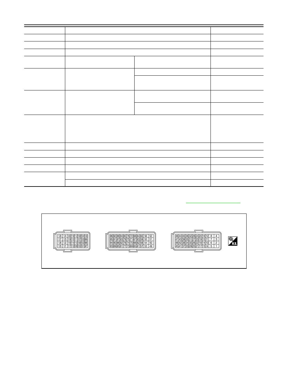
*2: Before measuring the terminal voltage, confirm that the battery is fully charged. Refer to
TERMINAL LAYOUT
PHYSICAL VALUES
NOTE:
• ECM is located behind the instrument assist lower panel. For this inspection, remove passenger side instru-
ment lower panel.
• Specification data are reference values and are measured between each terminal and ground.
• Pulse signal is measured by CONSULT-III.
LO SPEED CUT
• Ignition switch: ON
NON
AT OD MONITOR
• Ignition switch: ON
OFF
AT OD CANCEL
• Ignition switch: ON
OFF
CRUISE LAMP
• Ignition switch: ON
MAIN switch: Pressed at the 1st time
→
at the 2nd time
ON
→
OFF
SET LAMP
• MAIN switch: ON
• When vehicle speed is between 40
km/h (25 MPH) and 144 km/h (89
MPH)
ASCD: Operating
ON
ASCD: Not operating
OFF
EXH V/T LEARN
• Engine: Running
Exhaust Valve Timing Control Learning
has not been performed yet.
YET
Exhaust Valve Timing Control Learning
has not been performed yet.
CMPLT
BAT CUR SEN
• Engine speed: Idle
• Battery: Fully charged*
2
• Selector lever: P or N
• Air conditioner switch: OFF
• No load
Approx. 2,600 - 3,500 mV
ALT DUTY
• Engine: Idle
0 - 80%
A/F ADJ-B1
• Engine: Running
−
0.330 - 0.330
A/F ADJ-B2
• Engine: Running
−
0.330 - 0.330
FAN DUTY
• Engine: Running
0 - 100%
ALT DUTY SIG
• Power generation voltage variable control: Operating
ON
• Power generation voltage variable control: Not operating
OFF
Monitor Item
Condition
Values/Status
JMBIA0070ZZ
Нет комментариевНе стесняйтесь поделиться с нами вашим ценным мнением.
Текст