Infiniti FX35, FX50 (S51). Manual — part 1176
GAS SENSOR
HAC-101
< DTC/CIRCUIT DIAGNOSIS >
[AUTOMATIC AIR CONDITIONER]
C
D
E
F
G
H
J
K
L
M
A
B
HAC
N
O
P
Is the inspection result normal?
YES
>> Replace unified meter and A/C amp.
NO
>> Repair harnesses or connectors.
HAC-102
< DTC/CIRCUIT DIAGNOSIS >
[AUTOMATIC AIR CONDITIONER]
IONIZER
IONIZER
Description
INFOID:0000000005246294
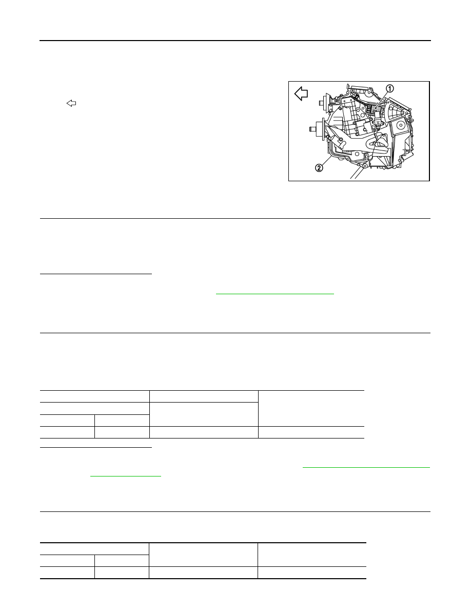
Ionizer (1) is attached to the heater & cooling unit assembly (2).
Ionizer has two types of operation mode and emits ions into the air
• Clean mode: Emits positive and negative ions at the same ratio.
• Ion control mode: Emits more negative ions.
Component Function Check
INFOID:0000000005246295
1.
CHECK IONIZER OPERATION SOUND
1.
Turn ignition switch ON.
2.
Press AUTO switch.
3.
Ion indicator is shown on the display.
4.
Check the ionizer operation sound (whirring sound) in the duct by putting an ear to the center ventilator
grille (LH) outlet.
Is the inspection result normal?
YES
>> INSPECTION END
NO
>> Go to Diagnosis Procedure. Refer to
HAC-102, "Diagnosis Procedure"
Diagnosis Procedure
INFOID:0000000005246296
1.
CHECK POWER SUPPLY FOR IONIZER
1.
Turn ignition switch OFF.
2.
Disconnect ionizer connector.
3.
Turn ignition switch ON.
4.
Press fan (UP: +) switch.
5.
Check voltage between ionizer harness connector and ground.
Is the inspection result normal?
YES
>> GO TO 2.
NO
>>
Check 10A fuse (No. 3, located in the fuse block). Refer to
PG-156, "Fuse, Connector and Ter-
.
• If fuse is OK, check harness for open circuit. Repair or replace if necessary.
• If fuse is NG, replace fuse and check for short circuit. Repair or replace if necessary.
2.
CHECK CIRCUIT CONTINUITY BETWEEN IONIZER AND GROUND
1.
Turn ignition switch OFF.
2.
Check continuity between ionizer harness connector and ground.
:
Vehicle front
JSIIA1148ZZ
(+)
(
−
)
Voltage
Ionizer
—
Connector
Terminal
M57
1
Ground
Battery voltage
Ionizer
—
Continuity
Connector
Terminal
M57
3
Ground
Existed

IONIZER
HAC-103
< DTC/CIRCUIT DIAGNOSIS >
[AUTOMATIC AIR CONDITIONER]
C
D
E
F
G
H
J
K
L
M
A
B
HAC
N
O
P
Is the inspection result normal?
YES
>> GO TO 3.
NO
>> Repair harnesses or connectors.
3.
CHECK ION ON/OFF SIGNAL
Check voltage between ionizer harness connector and ground.
Is the inspection result normal?
YES
>> Replace ionizer.
NO
>> GO TO 4.
4.
CHECK CIRCUIT CONTINUITY BETWEEN UNIFIED METER AND A/C AMP. AND IONIZER
1.
Turn ignition switch OFF.
2.
Disconnect unified meter and A/C amp. connector.
3.
Check continuity between unified meter and A/C amp. harness connector and ionizer harness connector.
4.
Check continuity between ionizer harness connector and ground.
Is the inspection result normal?
YES
>> Replace unified meter and A/C amp.
NO
>> Repair harnesses or connectors.
(+)
(
−
)
Condition
Voltage
Ionizer
—
Connector
Terminal
M57
4
Ground
Blower motor: OFF
12 V
Blower motor: ON
0 V
Ionizer
Unified meter and A/C amp.
Continuity
Connector
Terminal
Connector
Terminal
M57
4
M66
20
Existed
Ionizer
—
Continuity
Connector
Terminal
M57
4
Ground
Not existed

HAC-104
< ECU DIAGNOSIS INFORMATION >
[AUTOMATIC AIR CONDITIONER]
ECM
ECU DIAGNOSIS INFORMATION
ECM
VQ35HR
VQ35HR : Reference Value
INFOID:0000000005597998
VALUES ON THE DIAGNOSIS TOOL
NOTE:
• Specification data are reference values.
• Specification data are output/input values which are detected or supplied by the ECM at the connector.
* Specification data may not be directly related to their components signals/values/operations.
i.e. Adjust ignition timing with a timing light before monitoring IGN TIMING, because the monitor may show
the specification data in spite of the ignition timing not being adjusted to the specification data. This IGN TIM-
ING monitors the data calculated by the ECM according to the signals input from the camshaft position sen-
sor and other ignition timing related sensors.
CONSULT-III MONITOR ITEM
Monitor Item
Condition
Values/Status
ENG SPEED
• Run engine and compare CONSULT-III value with the tachometer indication.
Almost the same speed as
the tachometer indication
MAS A/F SE-B1
See
MAS A/F SE-B2
See
B/FUEL SCHDL
See
A/F ALPHA-B1
See
A/F ALPHA-B2
See
COOLAN TEMP/S
• Ignition switch: ON
Indicates engine coolant
temperature
A/F SEN1 (B1)
• Engine: After warming up
Maintaining engine speed at 2,000 rpm
Fluctuates around 2.2 V
A/F SEN1 (B2)
• Engine: After warming up
Maintaining engine speed at 2,000 rpm
Fluctuates around 2.2 V
HO2S2 (B1)
• Revving engine from idle to 3,000 rpm quickly after the following conditions are
met.
- Engine: After warming up
- After keeping engine speed between 3,500 and 4,000 rpm for 1 minute and at
idle for 1 minute under no load
0 - 0.3 V
←→
Approx. 0.6 -
1.0 V
HO2S2 (B2)
• Revving engine from idle to 3,000 rpm quickly after the following conditions are
met.
- Engine: After warming up
- After keeping engine speed between 3,500 and 4,000 rpm for 1 minute and at
idle for 1 minute under no load
0 - 0.3 V
←→
Approx. 0.6 -
1.0 V
HO2S2 MNTR (B1)
• Revving engine from idle to 3,000 rpm quickly after the following conditions are
met.
- Engine: After warming up
- After keeping engine speed between 3,500 and 4,000 rpm for 1 minute and at
idle for 1 minute under no load
LEAN
←→
RICH
HO2S2 MNTR (B2)
• Revving engine from idle to 3,000 rpm quickly after the following conditions are
met.
- Engine: After warming up
- After keeping engine speed between 3,500 and 4,000 rpm for 1 minute and at
idle for 1 minute under no load
LEAN
←→
RICH
VHCL SPEED SE
• Turn drive wheels and compare CONSULT-III value with the speedometer indi-
cation.
Almost the same speed as
speedometer indication
BATTERY VOLT
• Ignition switch: ON (Engine stopped)
11 - 14 V
ACCEL SEN 1
• Ignition switch: ON
(Engine stopped)
Accelerator pedal: Fully released
0.45 - 1.0 V
Accelerator pedal: Fully depressed
4.4 - 4.8 V
Нет комментариевНе стесняйтесь поделиться с нами вашим ценным мнением.
Текст