Infiniti FX35, FX50 (S51). Manual — part 48
ADP-184
< ECU DIAGNOSIS INFORMATION >
BCM (BODY CONTROL MODULE)
124
(LG)
Ground
Passenger door
switch
Input
Passenger door
switch
OFF (Door close)
8.5 - 9.0 V
ON (Door opene)
0 V
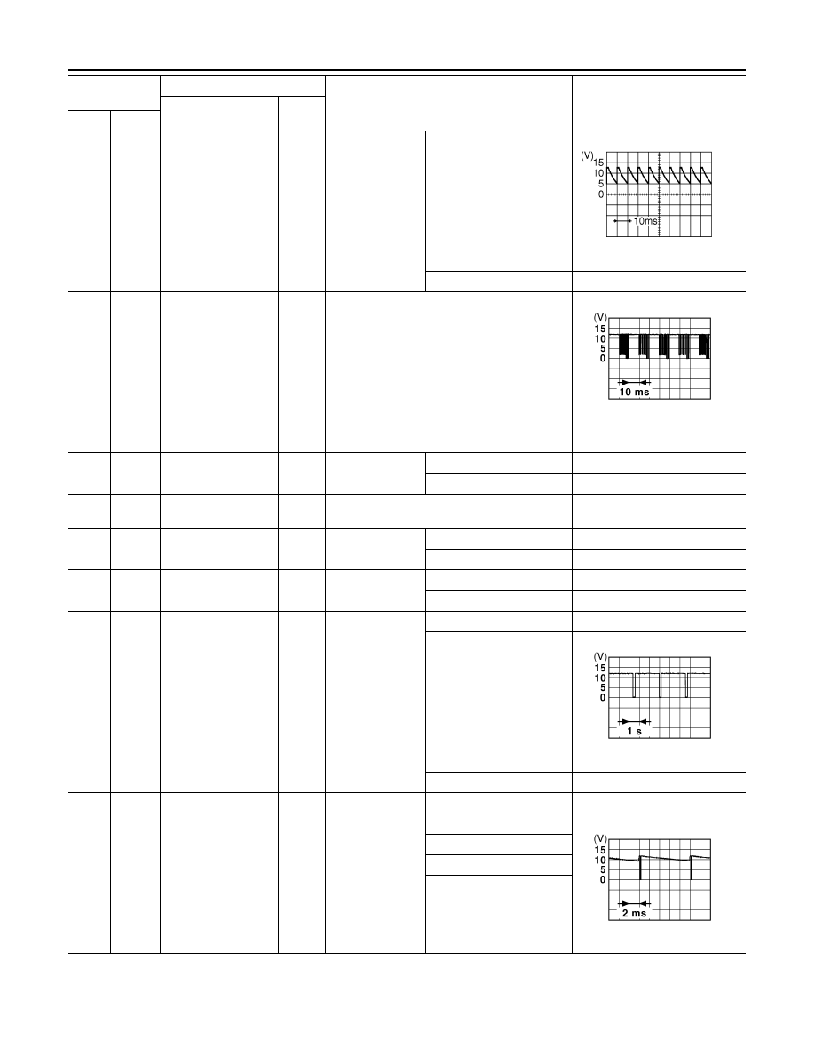
132
(O)
Ground
Power window switch
communication
Input/
Output
Ignition switch ON
10.2 V
Ignition switch OFF or ACC
12 V
134
(GR)
Ground
LOCK indicator lamp
Output
LOCK indicator
lamp
OFF
Battery voltage
ON
0 V
137
(B)
Ground
Receiver and sensor
ground
Input
Ignition switch ON
0 V
138
(Y)
Ground
Sensor power supply
Output
Ignition switch
OFF
0 V
ACC or ON
5.0 V
140
(R)
Ground
Selector lever P/N
position
Input
Selector lever
P or N position
12 V
Except P and N positions
0 V
141
(G)
Ground
Security indicator
Output
Security indicator
ON
0 V
Blinking
11.3 V
OFF
12 V
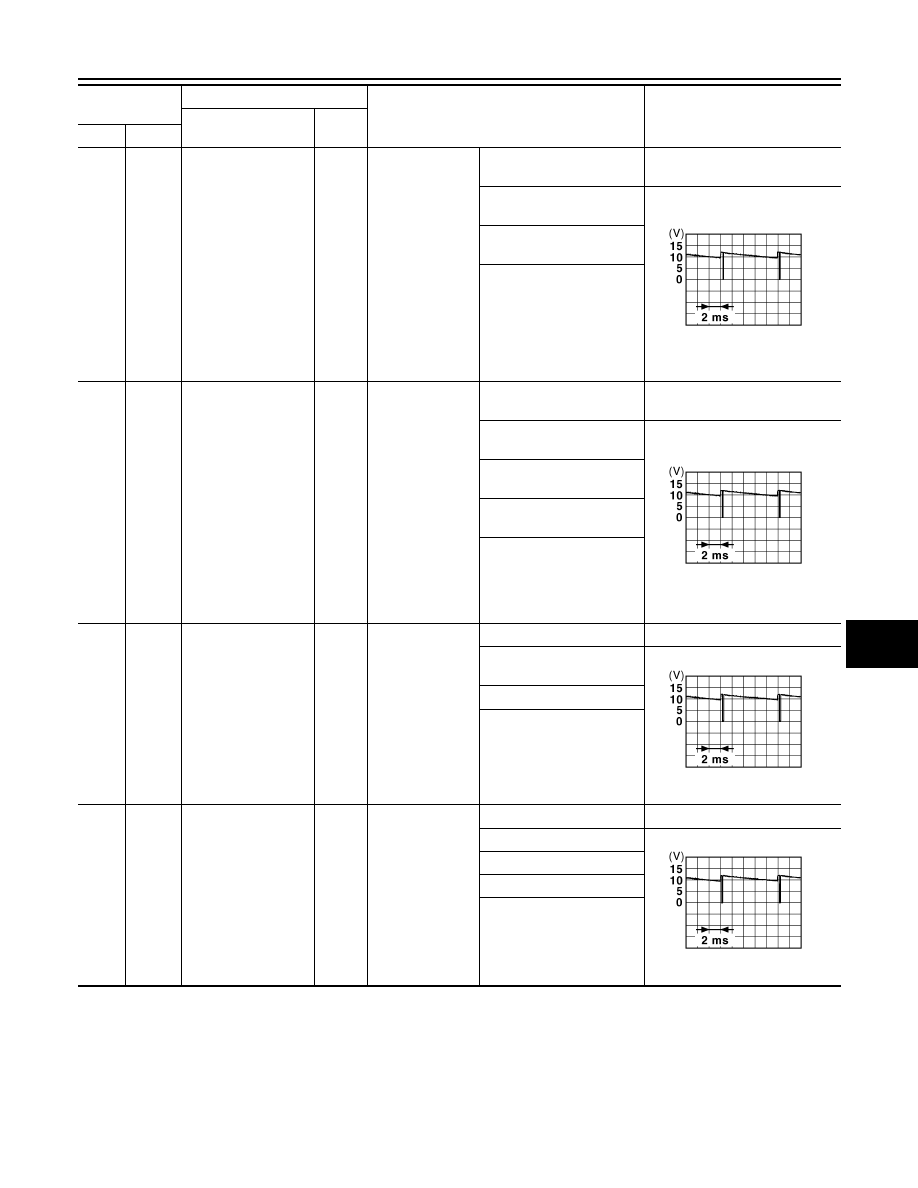
142
(O)
Ground
Combination switch
OUTPUT 5
Output
Combination
switch
(Wiper intermit-
tent dial 4)
All switches OFF
0 V
Lighting switch 1ST
10.7 V
Lighting switch HI
Lighting switch 2ND
Turn signal switch RH
Terminal No.
(Wire color)
Description
Condition
Value
(Approx.)
Signal name
Input/
Output
+
–
JPMIA0594GB
JPMIA0013GB
JPMIA0014GB
JPMIA0031GB
BCM (BODY CONTROL MODULE)
ADP-185
< ECU DIAGNOSIS INFORMATION >
C
D
E
F
G
H
I
K
L
M
A
B
ADP
N
O
P
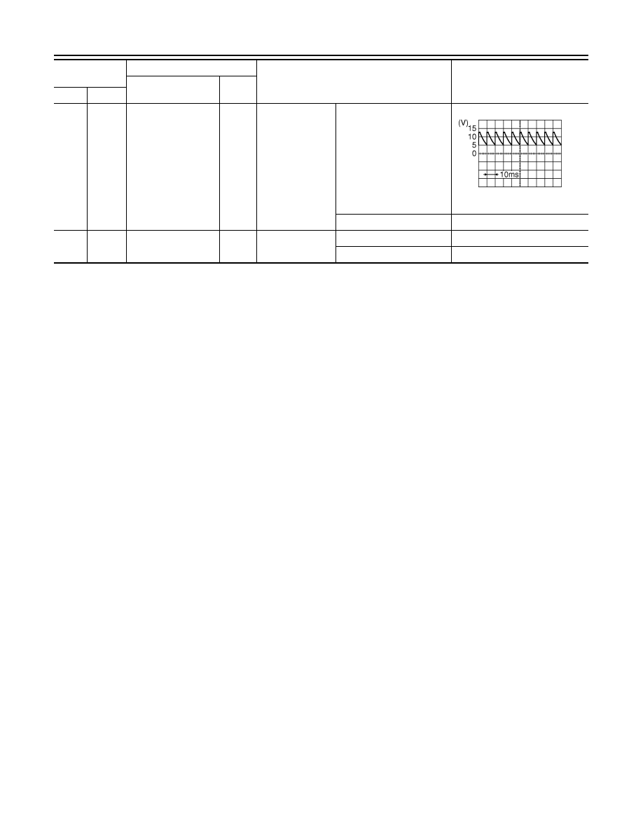
143
(P)
Ground
Combination switch
OUTPUT 1
Output
Combination
switch
All switches OFF
(Wiper intermittent dial 4)
0 V
Front wiper switch HI
(Wiper intermittent dial 4)
10.7 V
Rear wiper switch INT
(Wiper intermittent dial 4)
Any of the conditions below
with all switches OFF
• Wiper intermittent dial 1
• Wiper intermittent dial 2
• Wiper intermittent dial 3
• Wiper intermittent dial 6
• Wiper intermittent dial 7
144
(G)
Ground
Combination switch
OUTPUT 2
Output
Combination
switch
All switches OFF
(Wiper intermittent dial 4)
0 V
Front washer switch ON
(Wiper intermittent dial 4)
10.7 V
Rear wiper switch ON
(Wiper intermittent dial 4)
Rear washer switch ON
(Wiper intermittent dial 4)
Any of the conditions below
with all switches OFF
• Wiper intermittent dial 1
• Wiper intermittent dial 5
• Wiper intermittent dial 6
145
(L)
Ground
Combination switch
OUTPUT 3
Output
Combination
switch
(Wiper intermit-
tent dial 4)
All switches OFF
0 V
Front wiper switch INT/
AUTO
10.7 V
Front wiper switch LO
Lighting switch AUTO
146
(SB)
Ground
Combination switch
OUTPUT 4
Output
Combination
switch
(Wiper intermit-
tent dial 4)
All switches OFF
0 V
Front fog lamp switch ON
10.7 V
Lighting switch 2ND
Lighting switch PASS
Turn signal switch LH
Terminal No.
(Wire color)
Description
Condition
Value
(Approx.)
Signal name
Input/
Output
+
–
JPMIA0032GB
JPMIA0033GB
JPMIA0034GB
JPMIA0035GB
ADP-186
< ECU DIAGNOSIS INFORMATION >
BCM (BODY CONTROL MODULE)
150
(GR)
Ground
Driver door switch
Input
Driver door
switch
OFF (Door close)
8.5 - 9.0 V
ON (Door open)
0 V
151
(G)
Ground
Rear window defog-
ger relay control
Output
Rear window de-
fogger
Active
0 V
Not activated
Battery voltage
Terminal No.
(Wire color)
Description
Condition
Value
(Approx.)
Signal name
Input/
Output
+
–
JPMIA0594GB
BCM (BODY CONTROL MODULE)
ADP-187
< ECU DIAGNOSIS INFORMATION >
C
D
E
F
G
H
I
K
L
M
A
B
ADP
N
O
P
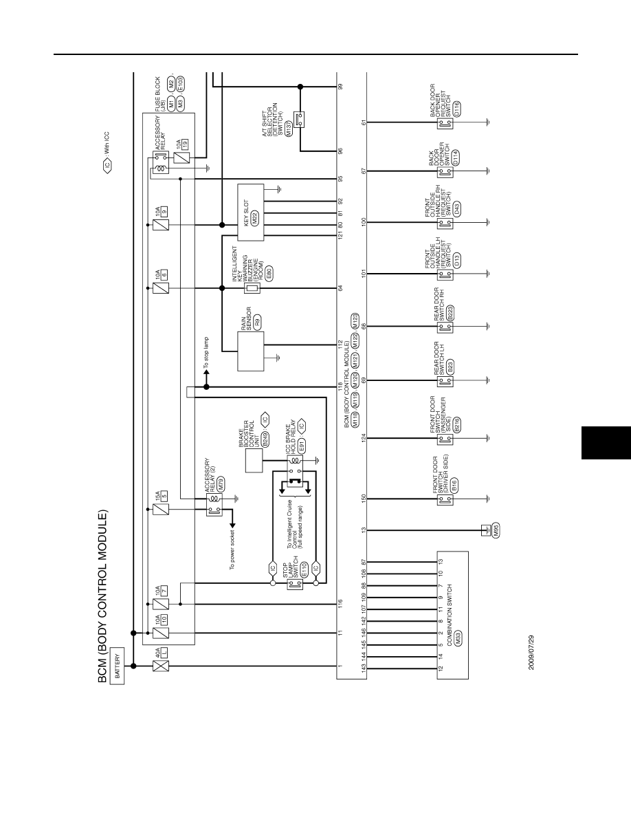
Wiring Diagram - BCM -
INFOID:0000000005700079
JCMWA4953GB
Нет комментариевНе стесняйтесь поделиться с нами вашим ценным мнением.
Текст