Infiniti FX35, FX50 (S51). Manual — part 767
MULTIPORT FUEL INJECTION SYSTEM
EC-609
< SYSTEM DESCRIPTION >
[VK50VE]
C
D
E
F
G
H
I
J
K
L
M
A
EC
N
P
O
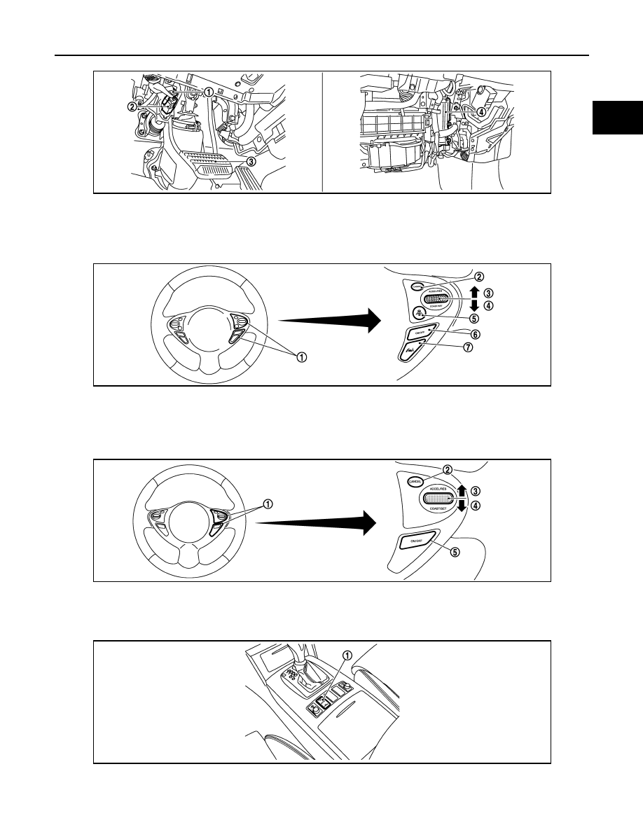
1.
Stop lamp switch
2.
ASCD brake switch (ASCD models)
ICC brake switch (ICC models)
3.
Brake pedal
4.
ECM
1.
ICC steering switch
2.
CANCEL switch
3.
RESUME/ACCELERATE switch
4.
SET/COAST switch
5.
DISTANCE switch
6.
MAIN switch
7.
LDP switch
1.
ASCD steering switch
2.
CANCEL switch
3.
RESUME/ACCELERATE switch
4.
SET/COAST switch
5.
MAIN switch
1.
Snow mode switch
JMBIA1509ZZ
JMBIA1507ZZ
JMBIA1508ZZ
JMBIA1623ZZ
EC-610
< SYSTEM DESCRIPTION >
[VK50VE]
MULTIPORT FUEL INJECTION SYSTEM
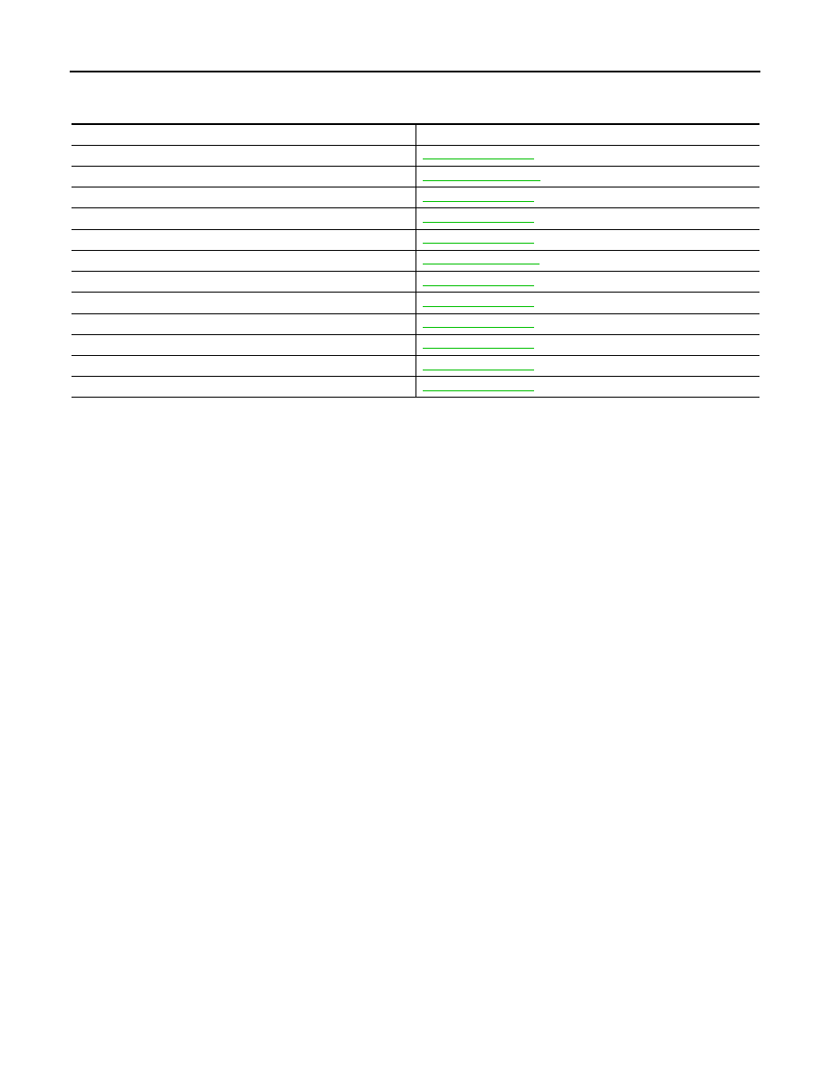
Component Description
INFOID:0000000005237175
Component
Reference
A/F sensor 1
Accelerator pedal position sensor
Camshaft position sensor
Crankshaft position sensor
Engine coolant temperature sensor
Fuel injector
Heated oxygen sensor 2
Intake air temperature sensor
Knock sensor
Mass air flow sensor
Power steering pressure sensor
Throttle position sensor
ELECTRIC IGNITION SYSTEM
EC-611
< SYSTEM DESCRIPTION >
[VK50VE]
C
D
E
F
G
H
I
J
K
L
M
A
EC
N
P
O
ELECTRIC IGNITION SYSTEM
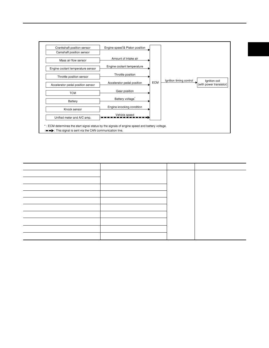
System Diagram
INFOID:0000000005237176
System Description
INFOID:0000000005237177
INPUT/OUTPUT SIGNAL CHART
*1: This signal is sent to the ECM via the CAN communication line.
*2: ECM determines the start signal status by the signals of engine speed and battery voltage.
SYSTEM DESCRIPTION
Ignition order: 1 - 8 - 7 - 3 - 6 - 5 - 4 - 2
The ignition timing is controlled by the ECM to maintain the best air-fuel ratio for every running condition of the
engine. The ignition timing data is stored in the ECM.
The ECM receives information such as the injection pulse width and camshaft position sensor signal. Comput-
ing this information, ignition signals are transmitted to the power transistor.
During the following conditions, the ignition timing is revised by the ECM according to the other data stored in
the ECM.
• At starting
• During warm-up
• At idle
• At low battery voltage
• During acceleration
The knock sensor retard system is designed only for emergencies. The basic ignition timing is programmed
within the anti-knocking zone, if recommended fuel is used under dry conditions. The retard system does not
JMBIA1527GB
Sensor
Input signal to ECM
ECM function
Actuator
Crankshaft position sensor
Engine speed*
2
Piston position
Ignition timing
control
Ignition coil
(with power transistor)
Camshaft position sensor
Mass air flow sensor
Amount of intake air
Engine coolant temperature sensor
Engine coolant temperature
Throttle position sensor
Throttle position
Accelerator pedal position sensor
Accelerator pedal position
TCM
Gear position
Battery
Battery voltage*
2
Knock sensor
Engine knocking
Unified meter and A/C amp.
Vehicle speed*
1
EC-612
< SYSTEM DESCRIPTION >
[VK50VE]
ELECTRIC IGNITION SYSTEM
operate under normal driving conditions. If engine knocking occurs, the knock sensor monitors the condition.
The signal is transmitted to the ECM. The ECM retards the ignition timing to eliminate the knocking condition.
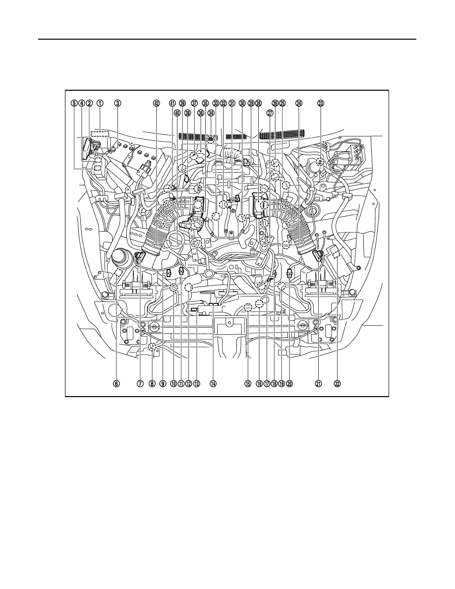
Component Parts Location
INFOID:0000000005589020
1.
IPDM E/R
2.
VVEL control module
3.
Battery current sensor
4.
VVEL actuator motor relay
5.
Cooling fan relay-1
6.
Cooling fan relay-2
7.
Mass air flow sensor (bank 2)
8.
Refrigerant pressure sensor
9.
Exhaust valve timing control position
sensor (bank 2)
10. Exhaust valve timing control sole-
noid valve (bank 2)
11.
Camshaft position sensor (bank 2)
12. Intake valve timing control solenoid
valve (bank 2)
13. Cooling fan motor-1
14. Cooling fan control module-1
15. Cooling fan motor-2
16. Cooling fan control module-2
17. Intake valve timing control solenoid
valve (bank 1)
18. Camshaft position sensor (bank 1)
19. Exhaust valve timing control sole-
noid valve (bank 1)
20. Exhaust valve timing control position
sensor (bank 1)
21. Mass air flow sensor (with intake air
temperature sensor) (bank 1)
22. ICC brake hold relay (ICC models)
23. Brake booster pressure sensor
24. Ignition coil (with power transistor)
and spark plug (bank 1)
25. VVEL actuator motor (bank 1)
26. VVEL control shaft position sensor
(bank 1)
27. Fuel injector (bank 1)
28. Electric throttle control actuator
(bank 1)
29. A/F sensor 1 (bank 1)
30. Knock sensor (bank 1)
JMBIA1535ZZ
Нет комментариевНе стесняйтесь поделиться с нами вашим ценным мнением.
Текст