Infiniti FX35, FX50 (S51). Manual — part 276
ABS ACTUATOR AND ELECTRIC UNIT (CONTROL UNIT)
BRC-135
< REMOVAL AND INSTALLATION >
[VDC/TCS/ABS]
C
D
E
G
H
I
J
K
L
M
A
B
BRC
N
O
P
7.
Remove ABS actuator and electric unit (control unit) bracket mounting nuts.
8.
Remove ABS actuator and electric unit (control unit) from vehicle.
INSTALLATION
Note the following, and install in the reverse order of removal.
• Before servicing, disconnect the battery cable from negative terminal.
• To remove brake tube, use a flare nut wrench to prevent flare nuts and brake tube from being damaged. To
install, use flare nut crowfoot and torque wrench.
• Never apply excessive impact to ABS actuator and electric unit (control unit), such as dropping it.
• Never remove and install actuator by holding harness.
• After work is completed, bleed air from brake tube. Refer to
BR-11, "Bleeding Brake System"
.
• After installing harness connector in the ABS actuator and electric unit (control unit), make sure harness
connector is securely locked.
• When replacing ABS actuator and electric unit (control unit), make sure to adjust neutral position of steering
angle sensor. Refer to
BRC-9, "ADJUSTMENT OF STEERING ANGLE SENSOR NEUTRAL POSITION :
.
BRC-136
< REMOVAL AND INSTALLATION >
[VDC/TCS/ABS]
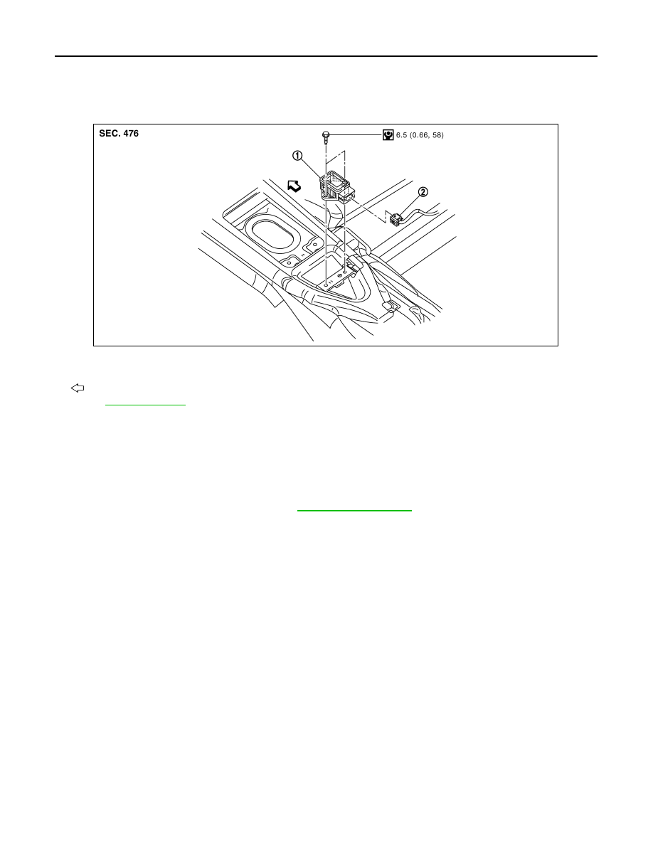
YAW RATE/SIDE G SENSOR
YAW RATE/SIDE G SENSOR
Exploded View
INFOID:0000000005234667
Removal and Installation
INFOID:0000000005234668
REMOVAL
CAUTION:
Never drop or strike yaw rate/side G sensor, or never use power tool etc., because yaw rate/side G
sensor is sensitive to the impact.
1.
Remove console finisher assembly. Refer to
.
2.
Disconnect yaw rate/side G sensor harness connector.
3.
Remove mounting bolts. Remove yaw rate/side G sensor.
INSTALLATION
Note the following, and install in the reverse order of removal.
• Never drop or strike yaw rate/side G sensor, or never use power tool etc., because yaw rate/side G sensor is
sensitive to the impact.
1.
Yaw rate/side G sensor
2.
Harness connector
: Vehicle front
Refer to
for symbol makes in the figure.
JSFIA0197GB
STEERING ANGLE SENSOR
BRC-137
< REMOVAL AND INSTALLATION >
[VDC/TCS/ABS]
C
D
E
G
H
I
J
K
L
M
A
B
BRC
N
O
P
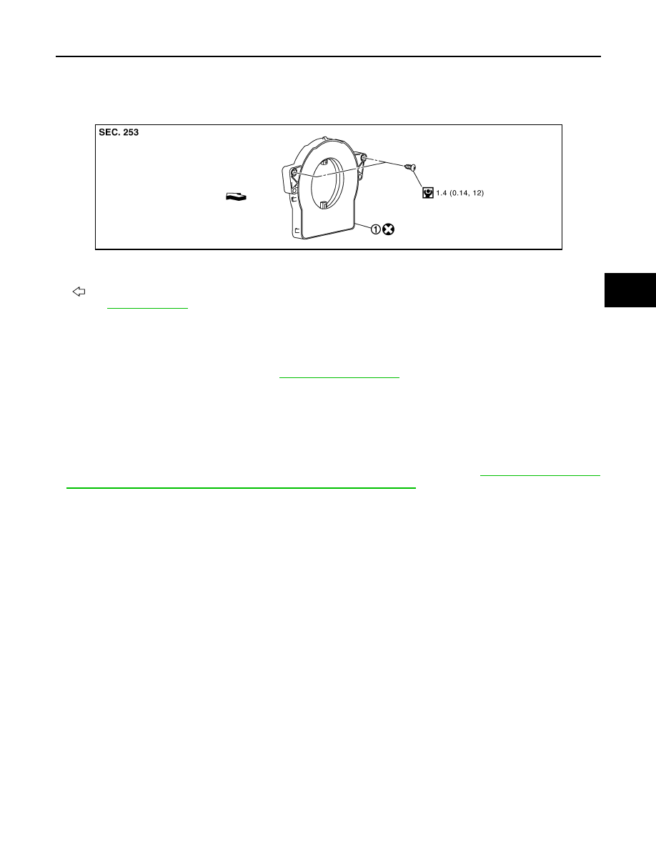
STEERING ANGLE SENSOR
Exploded View
INFOID:0000000005234669
Removal and Installation
INFOID:0000000005234670
REMOVAL
1.
Remove spiral cable assembly. Refer to
2.
Remove steering angle sensor from spiral cable assembly.
INSTALLATION
Note the following, and install in the reverse order of removal.
• Never reuse steering angle sensor.
• When installing steering angle sensor, tighten it to the specified torque with an electric screwdriver. Be sure
to tighten it completely with no floating and tilting.
• After work, make sure to adjust neutral position of steering angle sensor. Refer to
OF STEERING ANGLE SENSOR NEUTRAL POSITION : Description"
1.
Steering angle sensor
: Vehicle front
Refer to
for symbol marks in the figure.
JSFIA0237GB
BRC-138
< SYSTEM DESCRIPTION >
[BRAKE ASSIST]
PREVIEW FUNCTION
SYSTEM DESCRIPTION
PREVIEW FUNCTION
System Description
INFOID:0000000005234671
FUNCTION DESCRIPTION
When the Preview Function identifies the need to apply emergency braking by sensing a vehicle ahead in the
same lane and the distance and relative speed from it, it applies the brake pre-pressure before the driver
depress the brake pedal and helps improve brake response by reducing pedal free play.
The Preview Function shares component parts and diagnosis with the ICC (Intelligent Cruise Control) system.
CAUTION:
This system is only an aid to assist braking operation and is not a collision warning or avoidance
device. It is the driver
′
s responsibility to stay alert, drive safely and be in control of the vehicle at all
times.
OPERATION DESCRIPTION
Operation
• The system detects the distance to the vehicle in front with the ICC sensor integrated unit of ICC (Full Speed
Range) and judges the necessity of emergency braking.
• The system detects the accelerator pedal release operation of the driver by the accelerator pedal position
sensor and estimates the driver's brake operation intention.
• If the system is judged that the emergency braking is necessary or that the driver has the intention to oper-
ate the brake it supplies the power supply to the brake booster to apply pre-pressure and adjusts the brake
play.
NOTE:
This system will not operate when the vehicle is moving at approximately 32 km/h (20 MPH) or less.
End of Operation
The pre-pressure function ceases when the following conditions are met:
1.
When the driver depresses the accelerator pedal or the brake pedal.
2.
If the driver does not operate the accelerator pedal or brake pedal within approximately 1 second.
Нет комментариевНе стесняйтесь поделиться с нами вашим ценным мнением.
Текст