Infiniti FX35, FX50 (S51). Manual — part 275
WHEEL SENSOR
BRC-131
< REMOVAL AND INSTALLATION >
[VDC/TCS/ABS]
C
D
E
G
H
I
J
K
L
M
A
B
BRC
N
O
P
REMOVAL AND INSTALLATION
WHEEL SENSOR
FRONT WHEEL SENSOR
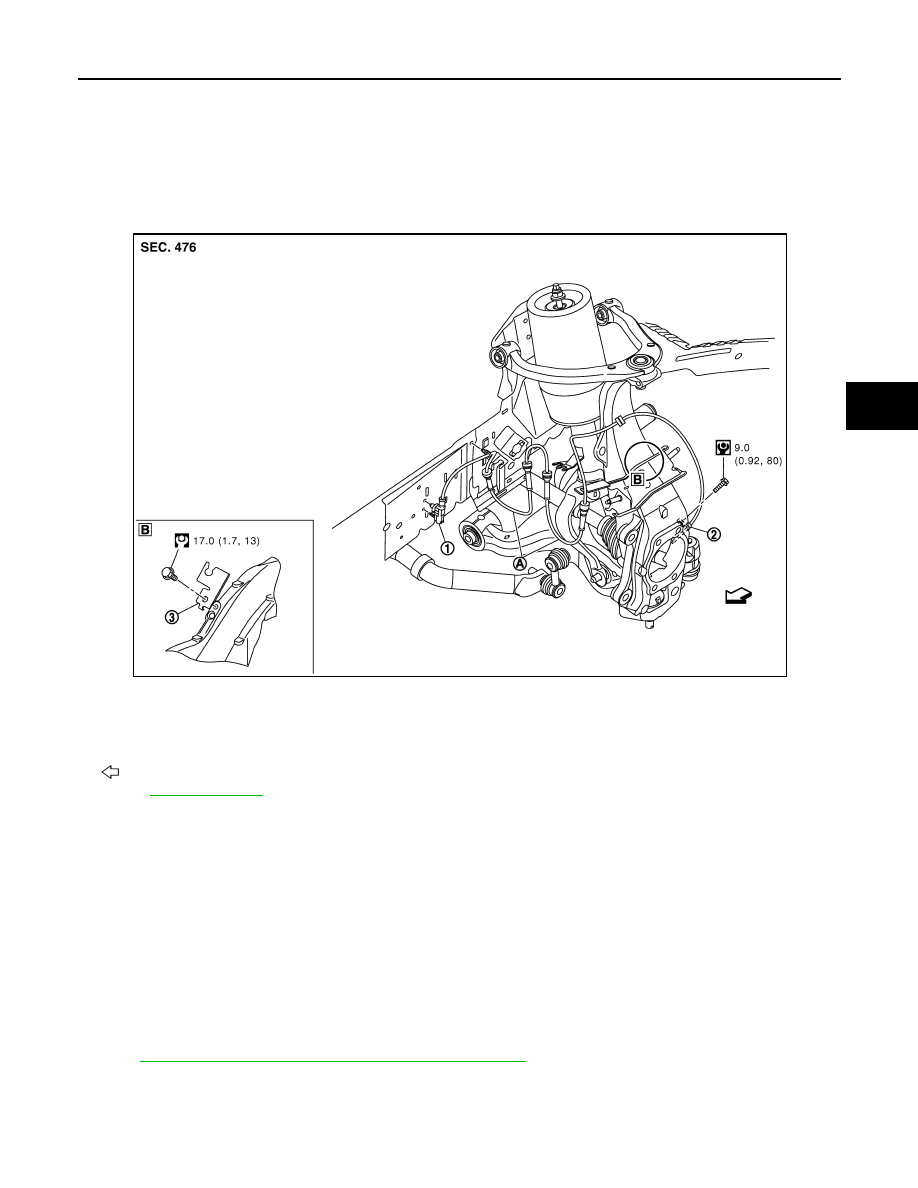
FRONT WHEEL SENSOR : Exploded View
INFOID:0000000005234657
NOTE:
The above figure shows left side. Right side is the mirror image.
FRONT WHEEL SENSOR : Removal and Installation
INFOID:0000000005234658
REMOVAL
Be careful with the following when removing sensor.
• Never twist sensor harness as much as possible, when removing it. Pull sensors out without pulling sensor
harness.
• Be careful to avoid damaging sensor edges or rotor teeth. Remove wheel sensor first before removing front
or rear wheel hub. This is to avoid damage to sensor wiring and loss of sensor function.
INSTALLATION
Be careful with the following when installing wheel sensor. Tighten installation bolts to the specified torques.
Refer to
BRC-131, "FRONT WHEEL SENSOR : Exploded View"
.
• When installing, make sure there is no foreign material such as iron chips on and in the mounting hole of the
wheel sensor. Make sure no foreign material has been caught in the sensor rotor. Remove any foreign mate-
rial and clean the mount.
1.
Front LH wheel sensor harness con-
nector
2.
Front LH wheel sensor
3.
Bracket
A.
White line (slant line)
: Vehicle front
Refer to
for symbol marks in the figure.
JSFIA0194GB
BRC-132
< REMOVAL AND INSTALLATION >
[VDC/TCS/ABS]
WHEEL SENSOR
• When installing wheel sensor, be sure to press rubber grommets in until they lock at locations shown above
in the figure. When installed, harness must not be twisted.
• When you see the harness of the wheel sensor from the front side of the vehicle ensure that the white lines
(A) are not twisted.
REAR WHEEL SENSOR
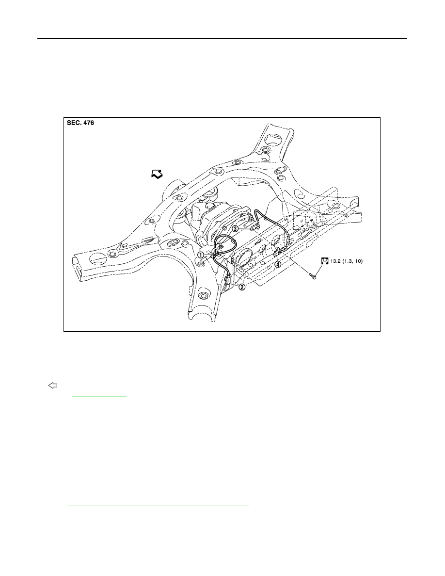
REAR WHEEL SENSOR : Exploded View
INFOID:0000000005234659
REAR WHEEL SENSOR : Removal and Installation
INFOID:0000000005234660
REMOVAL
Be careful with the following when removing sensor.
• Never twist sensor harness as much as possible, when removing it. Pull sensors out without pulling sensor
harness.
• Be careful to avoid damaging sensor edges or rotor teeth. Remove wheel sensor first before removing front
or rear wheel hub. This is to avoid damage to sensor wiring and loss of sensor function.
INSTALLATION
Be careful with the following when installing wheel sensor. Tighten installation bolts to the specified torques.
Refer to
BRC-132, "REAR WHEEL SENSOR : Exploded View"
.
• When installing, make sure there is no foreign material such as iron chips on and in the mounting hole of the
wheel sensor. Make sure no foreign material has been caught in the sensor rotor. Remove any foreign mate-
rial and clean the mount.
• When installing a rear LH wheel sensor, be sure to pass the wheel sensor harness under the breather hose.
1.
Rear LH wheel sensor
2.
Rear LH wheel sensor harness con-
nector
3.
Rear RH wheel sensor
4.
Rear RH wheel sensor harness con-
nector
: Vehicle front
Refer to
for symbol marks in the figure.
JSFIA0225GB
SENSOR ROTOR
BRC-133
< REMOVAL AND INSTALLATION >
[VDC/TCS/ABS]
C
D
E
G
H
I
J
K
L
M
A
B
BRC
N
O
P
SENSOR ROTOR
FRONT SENSOR ROTOR
FRONT SENSOR ROTOR : Exploded View
INFOID:0000000005234661
(2WD models),
(AWD models).
FRONT SENSOR ROTOR : Removal and Installation
INFOID:0000000005234662
REMOVAL
Sensor rotor cannot be disassembled. Remove the sensor rotor together with hub bearing assembly. Refer to
(2WD models),
(AWD models).
INSTALLATION
Sensor rotor cannot be disassembled. Install the sensor rotor together with hub bearing assembly. Refer to
(2WD models),
(AWD models).
REAR SENSOR ROTOR
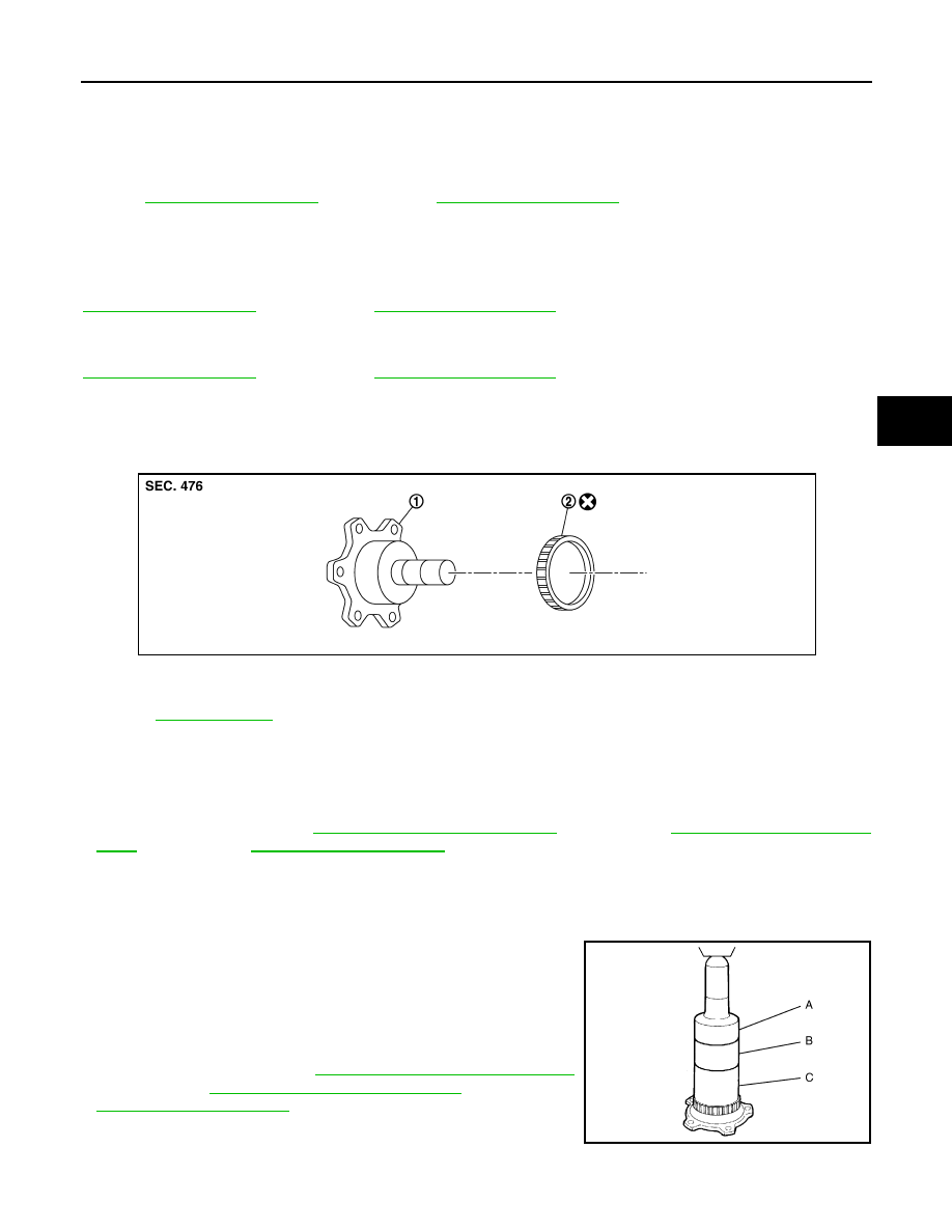
REAR SENSOR ROTOR : Exploded View
INFOID:0000000005234663
REAR SENSOR ROTOR : Removal and Installation
INFOID:0000000005234664
REMOVAL
• Follow the procedure below to remove rear sensor rotor.
- Remove side flange. Refer to
DLN-211, "2WD : Exploded View"
[R200 (2WD)],
[R200 (AWD)],
- Using a bearing replacer (suitable tool) and puller (suitable tool), remove sensor rotor from side flange.
INSTALLATION
CAUTION:
Never reuse sensor rotor.
• Follow the procedure below to install rear sensor rotor.
- Using a drifts, press rear sensor rotor onto side flange.
- Install side flange. Refer to
DLN-211, "2WD : Exploded View"
[R200 (2WD)],
DLN-224, "AWD : Exploded View"
[R200 (AWD)],
(R230).
1.
Side flange
2.
Rear wheel sensor rotor
Refer to
for symbol marks in the figure.
JSFIA0054JP
A: Drift [SST: ST30720000 (J-25405)]
B: Drift [SST: ST27863000 (
—
)]
C: Drift [SST: KV40104710 (
—
)]
SFIA3387E
BRC-134
< REMOVAL AND INSTALLATION >
[VDC/TCS/ABS]
ABS ACTUATOR AND ELECTRIC UNIT (CONTROL UNIT)
ABS ACTUATOR AND ELECTRIC UNIT (CONTROL UNIT)
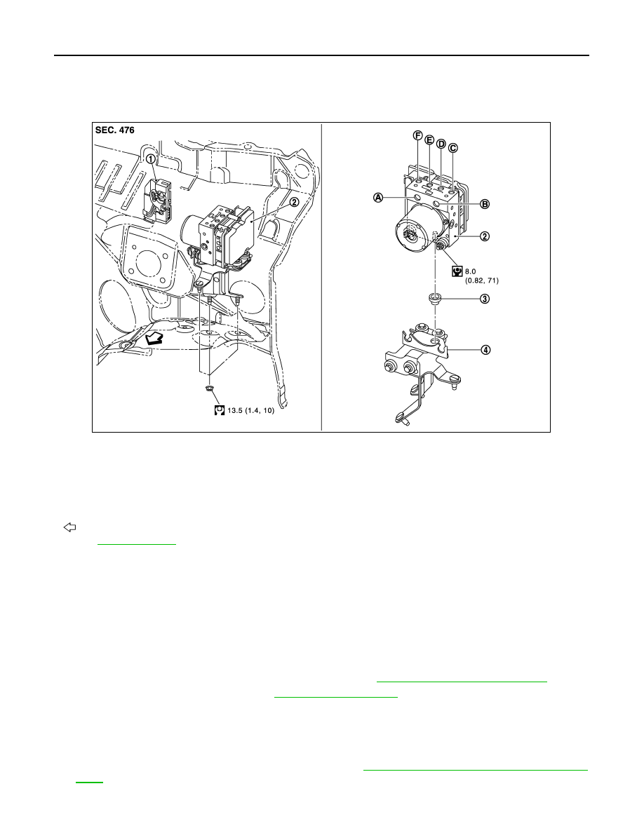
Exploded View
INFOID:0000000005234665
Removal and Installation
INFOID:0000000005234666
REMOVAL
CAUTION:
• Before servicing, disconnect the battery cable from negative terminal.
• To remove brake tube, use a flare nut wrench to prevent flare nuts and brake tube from being dam-
aged. To install, use flare nut crowfoot and torque wrench.
• Never apply excessive impact to ABS actuator and electric unit (control unit), such as dropping it.
• Never remove and install actuator by holding harness.
• After work is completed, bleed air from brake tube. Refer to
BR-11, "Bleeding Brake System"
1.
Remove hoodledge cover (LH). Refer to
2.
Remove brake tube between brake master cylinder and the ABS actuator and electric unit (control unit)
from the vehicle.
3.
Loosen brake tube flare nuts, then remove brake tubes from ABS actuator and electric unit (control unit).
4.
Remove tire (front LH side).
5.
Remove fender protector (rear): (front LH side). Refer to
EXT-25, "FENDER PROTECTOR : Exploded
.
6.
Disconnect ABS actuator and electric unit (control unit) harness connector.
1.
Harness connector
2.
ABS actuator and electric unit (control
unit)
3.
Bushing
4.
Bracket
A.
From master cylinder secondary side B.
From master cylinder primary side
C.
To front LH brake caliper
D.
To rear RH brake caliper
E.
To rear LH brake caliper
F.
To front RH brake caliper
: Vehicle front
Refer to
for symbol marks in the figure.
JSFIA0226GB
Нет комментариевНе стесняйтесь поделиться с нами вашим ценным мнением.
Текст