Infiniti FX35, FX50 (S51). Manual — part 308
CCS-52
< SYSTEM DESCRIPTION >
[ICC (FULL SPEED RANGE)]
DIAGNOSIS SYSTEM (ICC SENSOR INTEGRATED UNIT)
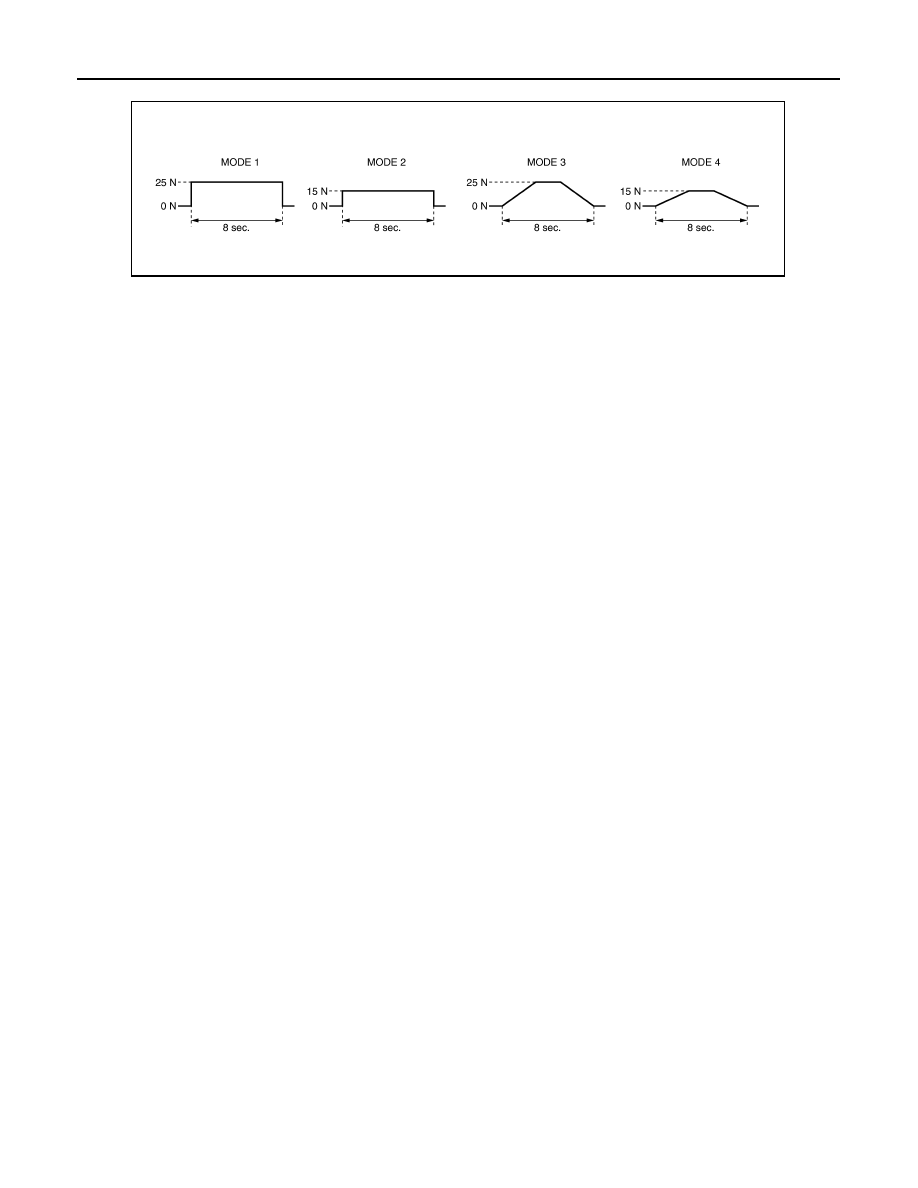
The test is finished in 10 seconds after starting.
JPOIA0061GB

CCS
C1A00 CONTROL UNIT
CCS-53
< DTC/CIRCUIT DIAGNOSIS >
[ICC (FULL SPEED RANGE)]
C
D
E
F
G
H
I
J
K
L
M
B
N
P
A
DTC/CIRCUIT DIAGNOSIS
C1A00 CONTROL UNIT
Description
INFOID:0000000005501573
ICC sensor integrated unit function description
• It detects the reflected light from the vehicle ahead by irradiating a laser forward. It calculates the vehicle dis-
tance from and relative speed with the vehicle ahead depending on the detected signal.
• It calculates the target vehicle distance and the target vehicle speed depending on the signals from various
sensors and switches, outputs the engine torque demand to ECM via CAN communication, and outputs the
brake fluid pressure command signal to the brake booster control unit via ITS communication.
DTC Logic
INFOID:0000000005501574
DTC DETECTION LOGIC
DTC CONFIRMATION PROCEDURE
1.
PERFORM DTC CONFIRMATION PROCEDURE
1.
Start the engine.
2.
Perform “All DTC Reading” with CONSULT-III.
3.
Check if the “C1A00” is detected as the current malfunction in “Self Diagnostic Result” of “ICC”.
Is “C1A00” detected as the current malfunction?
YES
>> Refer to
NO
>> INSPECTION END
Diagnosis Procedure
INFOID:0000000005501575
1.
CHECK SELF-DIAGNOSIS RESULTS
Check if any DTC other than “C1A00” is detected in “Self Diagnostic Result” of “ICC”.
Is any DTC detected?
YES
>> Perform diagnosis on the detected DTC and repair or replace the malfunctioning parts. Refer to
NO
>> Replace the ICC sensor integrated unit. Refer to
Special Repair Requirement
INFOID:0000000005501576
DESCRIPTION
Perform the action test after adjusting the laser beam aiming of ICC sensor integrated unit when the following
operation is performed.
• Removal and installation of ICC sensor integrated unit
• Replacement of ICC sensor integrated unit
SPECIAL REPAIR REQUIREMENT
1.
LASER BEAM AIMING ADJUSTMENT OF ICC SENSOR INTEGRATED UNIT
Adjust the laser beam aiming of the ICC sensor integrated unit. Refer to
>> GO TO 2.
DTC
(On board dis-
play)
Trouble diagnosis name
DTC detecting condition
Possible causes
C1A00
(0)
CONTROL UNIT
ICC sensor integrated unit internal malfunc-
tion
ICC sensor integrated unit
CCS-54
< DTC/CIRCUIT DIAGNOSIS >
[ICC (FULL SPEED RANGE)]
C1A00 CONTROL UNIT
2.
CHECK ICC SYSTEM
1.
Erase the “Self Diagnostic Result”, and then perform “All DTC Reading” again after performing the action
test. (Refer to
CCS-18, "ACTION TEST : Description"
2.
Check that the ICC system is normal.
>> WORK END

CCS
C1A01 POWER SUPPLY CIRCUIT 1, C1A02 POWER SUPPLY CIRCUIT 2
CCS-55
< DTC/CIRCUIT DIAGNOSIS >
[ICC (FULL SPEED RANGE)]
C
D
E
F
G
H
I
J
K
L
M
B
N
P
A
C1A01 POWER SUPPLY CIRCUIT 1, C1A02 POWER SUPPLY CIRCUIT 2
Description
INFOID:0000000005501577
The ICC sensor integrated unit controls the system with the ignition power supply.
DTC Logic
INFOID:0000000005501578
DTC DETECTION LOGIC
DTC CONFIRMATION PROCEDURE
1.
PERFORM DTC CONFIRMATION PROCEDURE
1.
Start the engine.
2.
Turn the MAIN switch of ICC system ON.
3.
Perform “All DTC Reading” with CONSULT-III.
4.
Check if the “C1A01” or “C1A02” is detected as the current malfunction in “Self Diagnostic Result” of
“ICC”.
Is “C1A01” or “C1A02” detected as the current malfunction?
YES
>> Refer to
NO
>> Refer to
GI-36, "Intermittent Incident"
.
Diagnosis Procedure
INFOID:0000000005501579
1.
CHECK ICC SENSOR INTEGRATED UNIT POWER SUPPLY AND GROUND CIRCUIT
Check power supply and ground circuit of ICC sensor integrated unit. Refer to
GRATED UNIT : Diagnosis Procedure"
Is the inspection result normal?
YES
>> Replace the ICC sensor integrated unit. Refer to
NO
>> Repair or replace the malfunctioning parts.
Special Repair Requirement
INFOID:0000000005501580
DESCRIPTION
Perform the action test after adjusting the laser beam aiming of ICC sensor integrated unit when the following
operation is performed.
• Removal and installation of ICC sensor integrated unit
• Replacement of ICC sensor integrated unit
SPECIAL REPAIR REQUIREMENT
1.
LASER BEAM AIMING ADJUSTMENT OF ICC SENSOR INTEGRATED UNIT
Adjust the laser beam aiming of the ICC sensor integrated unit. Refer to
>> GO TO 2.
2.
CHECK ICC SYSTEM
1.
Erase the “Self Diagnostic Result”, and then perform “All DTC Reading” again after performing the action
test. (Refer to
CCS-18, "ACTION TEST : Description"
DTC
(On board dis-
play)
Trouble diagnosis
name
DTC detecting condition
Possible causes
C1A01
(1)
POWER SUPPLY
CIR
ICC sensor integrated unit power supply voltage
is excessively low (less than 8 V).
• Connector, harness, fuse
• ICC sensor integrated unit
C1A02
(2)
POWER SUPPLY
CIR 2
ICC sensor integrated unit power supply voltage
is excessively high (more than 19 V).
Нет комментариевНе стесняйтесь поделиться с нами вашим ценным мнением.
Текст