Infiniti FX35, FX50 (S51). Manual — part 307

CCS-48
< SYSTEM DESCRIPTION >
[ICC (FULL SPEED RANGE)]
DIAGNOSIS SYSTEM (ICC SENSOR INTEGRATED UNIT)
THRTL SENSOR
[deg]
×
NOTE:
The item is displayed, but it is not monitored.
ENGINE RPM
[rpm]
Indicates engine speed read from ICC sensor integrated unit through CAN communi-
cation (ECM transmits engine speed through CAN communication).
WIPER SW
[Off/Low/High]
Indicates wiper [Off/Low/High] status (BCM transmits front wiper request signal
through CAN communication).
YAW RATE
[deg/s]
NOTE:
The item is displayed, but it is not monitored.
BA WARNING
[On/Off]
Indicates [On/Off] status of IBA OFF indicator lamp output.
FUNC ITEM
[FUNC1]
Indicates the equipment status of DCA system and LDP system.
LDP SELECT
[On/Off]
Indicates [On/Off] status of LDP system setting displayed on the navigation screen.
DCA SELECT
[On/Off]
Indicates [On/Off] status of DCA system setting displayed on the navigation screen.
RELEASE SW NO
[On/Off]
Indicates [On/Off] status as judged from release switch signal.
ON: When brake pedal is depressed.
OFF: When brake pedal is not depressed.
RELEASE SW NC
[On/Off]
Indicates [On/Off] status as judged from release switch signal.
ON: When brake pedal is not depressed.
OFF: When brake pedal is depressed.
STP LMP DRIVE
[On/Off]
×
Indicates [On/Off] status of ICC brake hold relay drive output.
PRESS SENS
[bar]
×
Indicates brake fluid pressure value calculated from signal voltage of brake pressure
sensor.
D RANGE SW
[On/Off]
Indicates [On/Off] status of “D” or “DS” or “M” positions read from ICC sensor integrat-
ed unit through CAN communication; ON when position “D” or “DS” or “M” (TCM
transmits shift position signal through CAN communication).
NP RANGE SW
[On/Off]
Indicates shift position signal read from ICC sensor integrated unit through CAN com-
munication (TCM transmits shift position signal through CAN communication).
PKB SW
[On/Off]
Parking brake switch status [On/Off] judged from the parking brake switch signal that
ICC sensor integrated unit readout via CAN communication is displayed (Unified
meter and A/C amp. transmits the parking brake switch signal via CAN communica-
tion).
PWR SUP MONI
[V]
×
Indicates IGN voltage input by ICC sensor integrated unit.
VHCL SPD AT
[km/h] or [mph]
Indicates vehicle speed calculated from A/T vehicle speed sensor read from ICC sen-
sor integrated unit through CAN communication (TCM transmits A/T vehicle speed
sensor signal through CAN communication).
THRTL OPENING
[%]
×
Indicates throttle position read from ICC sensor integrated unit through CAN commu-
nication (ECM transmits accelerator pedal position signal through CAN communica-
tion).
GEAR
[1, 2, 3, 4, 5, 6, 7]
Indicates A/T gear position read from ICC sensor integrated unit through CAN com-
munication (TCM transmits current gear position signal through CAN communica-
tion).
CLUTCH SW SIG
[On/Off]
×
NOTE:
The item is displayed, but it is not monitored.
NP SW SIG
[On/Off]
×
NOTE:
The item is displayed, but it is not used.
MODE SIG
[OFF, ICC, ASCD]
Indicates the active mode from ICC or ASCD [conventional (fixed speed) cruise con-
trol mode].
SET DISP IND
[On/Off]
Indicates [On/Off] status of SET switch indicator output.
Monitored item
[Unit]
MAIN
SIGNAL
Description

CCS
DIAGNOSIS SYSTEM (ICC SENSOR INTEGRATED UNIT)
CCS-49
< SYSTEM DESCRIPTION >
[ICC (FULL SPEED RANGE)]
C
D
E
F
G
H
I
J
K
L
M
B
N
P
A
ACTIVE TEST
CAUTION:
• Never perform “Active Test” while driving the vehicle.
• The “Active Test” cannot be performed when the ICC system warning lamp is illuminated.
• Shift the selector lever to “P” position, and then perform the test.
METER LAMP
NOTE:
The test can be performed only when the engine is running.
LDP SYSTEM ON
[On/Off]
Indicates [On/Off] status of LDP system.
LDW SYSTEM ON
[On/Off]
Indicates [On/Off] status of LDW system.
FCW SYSTEM ON
[On/Off]
Indicates [On/Off] status of FCW system.
DISTANCE
[m]
Indicates the distance from the vehicle ahead.
RELATIVE SPD
[m/s]
Indicates the relative speed of the vehicle ahead.
DCA ON SW
[On/Off]
×
NOTE:
The item is displayed, but it is not used.
DCA ON IND
[On/Off]
The status [On/Off] of DCA system switch indicator output is displayed.
DCA VHL AHED
[On/Off]
The status [On/Off] of vehicle ahead detection indicator output in DCA system is dis-
played.
IBA SW
[On/Off]
Status [On/Off] judged from IBA OFF switch signal that ICC sensor integrated unit
readout via ITS communication is displayed (Brake booster control unit transmits the
IBA OFF switch signal via ITS communication).
DYNA ASIST SW
[On/Off]
Indicates [On/Off] status as judged from ICC steering switch signal (DCA switch sig-
nal) [ECM transmits ICC steering switch signal (DCA switch signal) through CAN
communication].
APA TEMP
[
°
C]
The accelerator pedal actuator integrated motor temperature that the ICC sensor in-
tegrated unit readout via ITS communication is displayed (Accelerator pedal actuator
transmits the integrated motor temperature via ITS communication).
APA PWR
[V]
Accelerator pedal actuator power supply voltage that the ICC sensor integrated unit
readout via ITS communication is displayed (Accelerator pedal actuator transmits the
power supply voltage via ITS communication).
Monitored item
[Unit]
MAIN
SIGNAL
Description
Test item
Description
METER LAMP
The ICC system warning lamp, MAIN switch indicator, SET switch indicator and IBA OFF indicator
lamp can be illuminated by ON/OFF operations as necessary.
DCA INDICATOR
The DCA system switch indicator can be illuminated by ON/OFF operations as necessary.
STOP LAMP
The ICC brake hold relay can be operated by ON/OFF operations as necessary, and the stop lamp
can be illuminated.
BOOSTER SOL/V
The booster solenoid can be operated as necessary, and the brake can be operated.
ICC BUZZER
The ICC warning chime can sound by ON/OFF operations as necessary.
ACCELERATOR PEDAL AC-
TUATOR
The accelerator pedal actuator can be operated as necessary.

CCS-50
< SYSTEM DESCRIPTION >
[ICC (FULL SPEED RANGE)]
DIAGNOSIS SYSTEM (ICC SENSOR INTEGRATED UNIT)
DCA INDICATOR
NOTE:
The test can be performed only when the engine is running.
STOP LAMP
BOOSTER SOL/V
NOTE:
The test can be performed only when the engine is running.
NOTE:
Test item
Oper-
ation
Description
• MAIN switch indicator
• SET switch indicator
• ICC system warning lamp
• IBA OFF indicator lamp
METER LAMP
Off
Stops transmitting the signals below to end the test.
• Meter display signal
• ICC warning lamp signal
• IBA OFF indicator lamp signal
OFF
On
Transmits the following signals to the unified meter and A/C
amp. via CAN communication.
• Meter display signal
• ICC warning lamp signal
• IBA OFF indicator lamp signal
ON
Test item
Oper-
ation
Description
DCA system switch indicator
DCA INDICATOR
Off
Stops transmitting the DCA system switch indicator signal
below to end the test.
OFF
On
Transmits the DCA system switch indicator signal to the uni-
fied meter and A/C amp. via CAN communication.
ON
Test item
Oper-
ation
Description
Stop lamp
STOP LAMP
Off
Stops transmitting the ICC brake hold relay drive signal be-
low to end the test.
OFF
On
Transmits the ICC brake hold relay drive signal to the brake
booster control unit via ITS communication.
ON
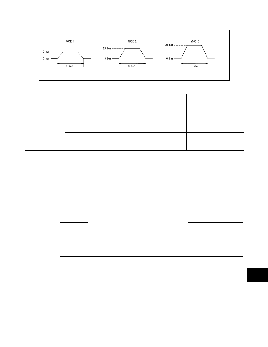
Test item
Operation
Description
“PRESS SENS” value
BOOSTER SOL/V
MODE1
Transmits the brake fluid pressure command signal to
the brake booster control unit via ITS communication.
10 bar
MODE2
20 bar
MODE3
30 bar
Test start
Starts the tests of “MODE1”, “MODE2” and “MODE3”.
—
Reset
Stops transmitting the brake fluid pressure command sig-
nal below to end the test.
—
End
Returns to the “SELECT TEST ITEM” screen.
—
CCS
DIAGNOSIS SYSTEM (ICC SENSOR INTEGRATED UNIT)
CCS-51
< SYSTEM DESCRIPTION >
[ICC (FULL SPEED RANGE)]
C
D
E
F
G
H
I
J
K
L
M
B
N
P
A
The test is finished in 10 seconds after starting.
ICC BUZZER
ACCELERATOR PEDAL ACTUATOR
CAUTION:
• Shift the selector lever to “P” position, and then perform the test.
• Never depress the accelerator pedal excessively. (The engine speed may rise unexpectedly when
finishing the test.)
NOTE:
• Depress the accelerator pedal to check when performing the test.
• The test can be performed only when the engine is running.
NOTE:
PKIB1767J
Test item
Operation
Description
ICC warning chime operation
sound
ICC BUZZER
MODE1
Transmits the buzzer output signal to the brake booster
control unit via ITS communication.
Intermittent beep sound
MODE2
Continuous beep sound
MODE3
Beep sound
Test start
Starts the tests of “MODE1”, “MODE2” and “MODE3”.
Reset
Stops transmitting the buzzer output signal below to end
the test.
—
End
Returns to the “SELECT TEST ITEM” screen.
Test item
Operation
Description
Accelerator pedal operation
ACCELERATOR
PEDAL ACTUA-
TOR
MODE1
Transmit the accelerator pedal feedback force control signal
to the accelerator pedal actuator via ITS communication.
Constant with a force of 25 N
for 8 seconds
MODE2
Constant with a force of 15 N
for 8 seconds
MODE3
Change up to a force of 25 N for
8 seconds
MODE4
Change up to a force of 15 N for
8 seconds
Test start
Starts the tests of “MODE1”, “MODE2”, “MODE3”, and
“MODE4”.
—
Reset
Stops transmitting the accelerator pedal feedback force
control signal below to end the test.
—
End
Returns to the “SELECT TEST ITEM” screen.
—
Нет комментариевНе стесняйтесь поделиться с нами вашим ценным мнением.
Текст