Infiniti FX35, FX50 (S51). Manual — part 1784
C1929 ABS ACTUATOR AND ELECTRIC UNIT (CONTROL UNIT)
STC-77
< DTC/CIRCUIT DIAGNOSIS >
[WITH REAR ACTIVE STEER]
C
D
E
F
H
I
J
K
L
M
A
B
STC
N
O
P
C1929 ABS ACTUATOR AND ELECTRIC UNIT (CONTROL UNIT)
Description
INFOID:0000000005549723
The ABS actuator and electric unit (control unit) and the RAS control unit exchange signals via the CAN com-
munication line.
DTC Logic
INFOID:0000000005549724
DTC DETECTION LOGIC
DTC CONFIRMATION PROCEDURE
NOTE:
Every time when “C1929” is detected, either the ABS actuator ad electric unit (control unit) or the RAS control
unit simultaneously detects a DTC that leads to a direct cause of the malfunction.
1.
DTC REPRODUCTION PROCEDURE
With CONSULT-III
1.
Turn the ignition switch from OFF to ON.
2.
Perform “4WAS(MAIN)/RAS/HICAS” self-diagnosis.
Without CONSULT-III
1.
Start the engine.
2.
Perform the self-diagnosis. Refer to
STC-38, "Diagnosis Description"
.
Is DTC “C1929” or “RAS warning lamp flickering pattern:26” detected?
YES
>> Proceed to diagnosis procedure. Refer to
NO
>> INSPECTION END
Diagnosis Procedure
INFOID:0000000005549725
1.
PERFORM SELF-DIAGNOSIS
With CONSULT-III
1.
Turn the ignition switch from OFF to ON.
2.
Perform “4WAS(MAIN)/RAS/HICAS” self-diagnosis.
Is DTC “U1000” or “U1010” detected?
YES
>> Check the malfunction system.
NO
>> GO TO 2.
2.
PERFORM ABS ACTUATOR AND ELECTRIC UNIT (CONTROL UNIT) SELF-DIAGNOSIS
With CONSULT-III
Perform “ABS” self-diagnosis.
Is DTC except “DTC related to a malfunction of RAS control unit” detected?
YES
>> Check the DTC. Refer to
NO
>> GO TO 3.
3.
PERFORM RAS CONTROL UNIT SELF-DIAGNOSIS
With CONSULT-III
Perform “4WAS(MAIN)/RAS/HICAS” self-diagnosis.
Is DTC except “C1929” detected?
YES
>> Check the DTC. Refer to
.
NO
>> GO TO 4.
4.
INFORMATION CHECK
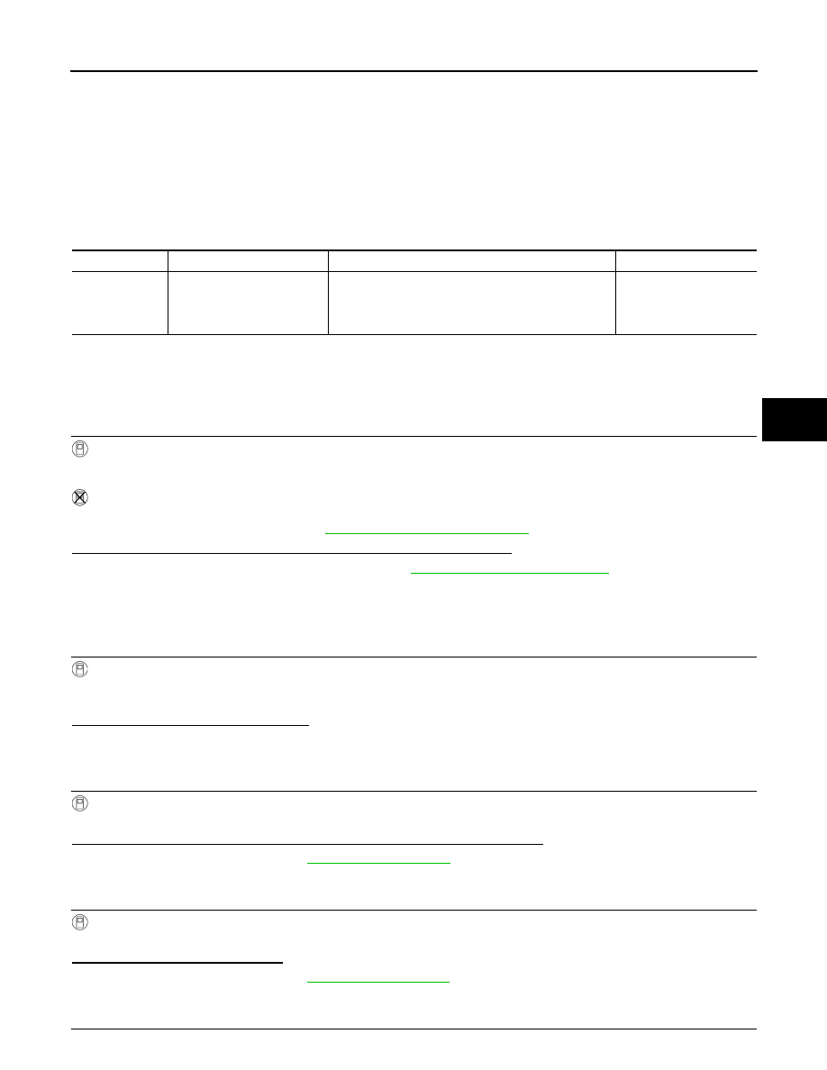
DTC
Display items
Malfunction detected condition
Possible cause
C1929
VDC
Malfunction is detected in VDC malfunction signal that
is output from ABS actuator and electric unit (control
unit) via CAN communication.
(VDC malfunction signal is improper.)
• ABS actuator and elec-
tric unit (control unit)
• CAN communication
• RAS control unit

STC-78
< DTC/CIRCUIT DIAGNOSIS >
[WITH REAR ACTIVE STEER]
C1929 ABS ACTUATOR AND ELECTRIC UNIT (CONTROL UNIT)
With CONSULT-III
1.
Select “DATA MONITOR” of “4WAS(MAIN)/RAS/HICAS”.
2.
Check the “DATA MONITOR” value of each DTC detected with the self-diagnosis function. Refer to
.
Is each data the standard value?
YES
>> Check that there is no malfunction in each harness connector pin terminal or disconnection.
NO
>> Replace RAS control unit. Refer to
STC-109, "Removal and Installation"
.
Special Repair Requirement
INFOID:0000000005549726
BEFORE REPLACING RAS CONTROL UNIT
• Record the self-diagnosis results (history).
CAUTION:
• Never erase the memory (history) of self-diagnosis results when replacing RAS control unit after
diagnosis.
• Erase the memory of the self-diagnosis results (record) after printing out or recording all the val-
ues of “DATA MONITOR”.
U1000 CAN COMM CIRCUIT
STC-79
< DTC/CIRCUIT DIAGNOSIS >
[WITH REAR ACTIVE STEER]
C
D
E
F
H
I
J
K
L
M
A
B
STC
N
O
P
U1000 CAN COMM CIRCUIT
Description
INFOID:0000000005549727
CAN (Controller Area Network) is a serial communication line for real time application. It is an on-vehicle mul-
tiplex communication line with high data communication speed and excellent error detection ability. Many elec-
tronic control units are equipped onto a vehicle, and each control unit shares information and links with other
control units during operation (not independent). In CAN communication, control units are connected with 2
communication lines (CAN-H line, CAN-L line) allowing a high rate of information transmission with less wiring.
Each control unit transmits/receives data but selectively reads required data only.
DTC Logic
INFOID:0000000005549728
DTC DETECTION LOGIC
DTC CONFIRMATION PROCEDURE
1.
DTC REPRODUCTION PROCEDURE
With CONSULT-III
1.
Turn the ignition switch from OFF to ON.
2.
Perform “4WAS(MAIN)/RAS/HICAS” self-diagnosis.
Is DTC “U1000” detected?
YES
>> Proceed to diagnosis procedure. Refer to
NO
>> INSPECTION END
Diagnosis Procedure
INFOID:0000000005549729
1.
PERFORM SELF-DIAGNOSIS
Perform “4WAS(MAIN)/RAS/HICAS” self-diagnosis.
Is DTC “U1000” detected?
YES
>> Perform CAN diagnosis. Refer to
LAN-29, "CAN System Specification Chart"
NO
>> INSPECTION END
Special Repair Requirement
INFOID:0000000005549730
BEFORE REPLACING RAS CONTROL UNIT
• Record the self-diagnosis results (history).
CAUTION:
• Never erase the memory (history) of self-diagnosis results when replacing RAS control unit after
diagnosis.
• Erase the memory of the self-diagnosis results (record) after printing out or recording all the val-
ues of “DATA MONITOR”.
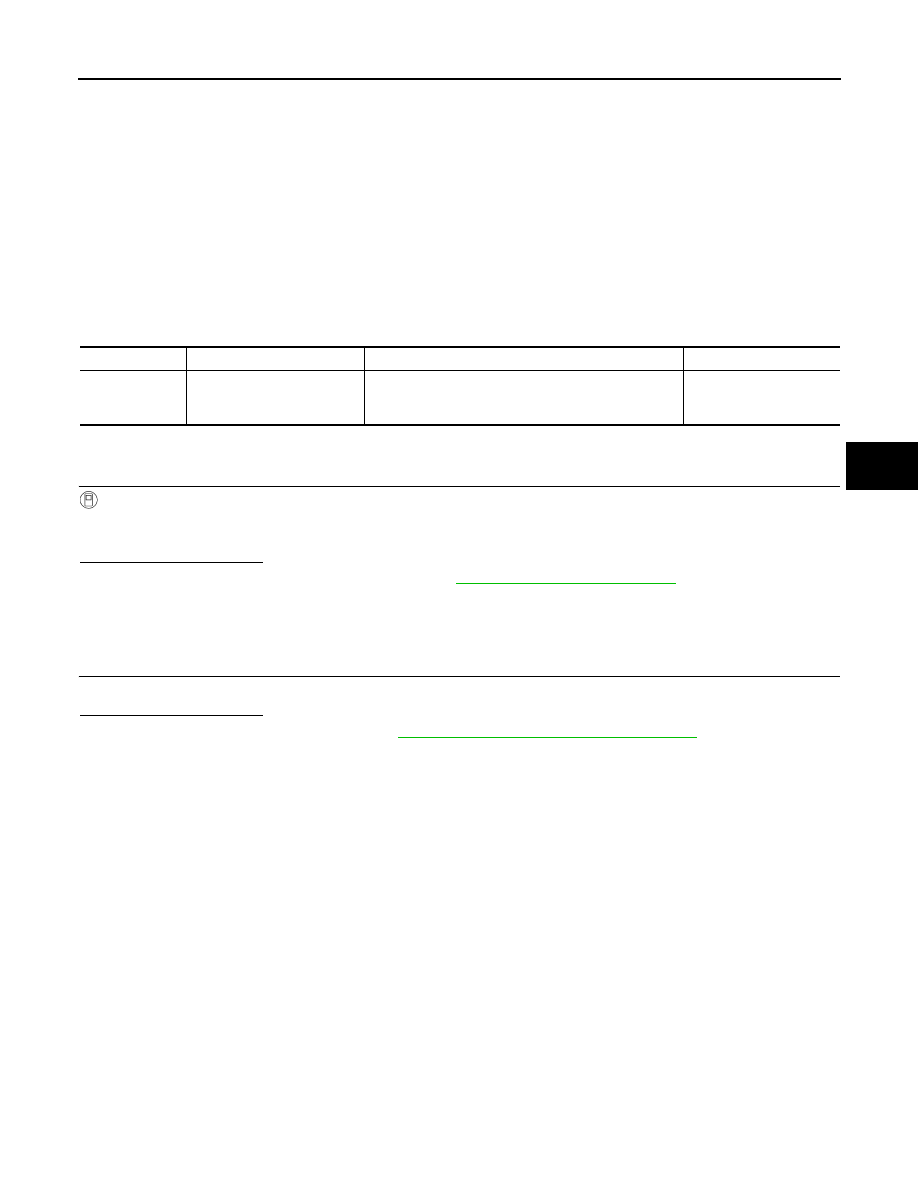
DTC
Display items
Malfunction detected condition
Possible cause
U1000
CAN COMM CIRCUIT
When RAS control unit is not transmitting or receiving
CAN communication signal for 2 seconds or more.
• CAN communication
line
• RAS control unit

STC-80
< DTC/CIRCUIT DIAGNOSIS >
[WITH REAR ACTIVE STEER]
U1010 CONTROL UNIT (CAN)
U1010 CONTROL UNIT (CAN)
Description
INFOID:0000000005549731
CAN (Controller Area Network) is a serial communication line for real time application. It is an on-vehicle mul-
tiplex communication line with high data communication speed and excellent error detection ability. Many elec-
tronic control units are equipped onto a vehicle, and each control unit shares information and links with other
control units during operation (not independent). In CAN communication, control units are connected with 2
communication lines (CAN-H line, CAN-L line) allowing a high rate of information transmission with less wiring.
Each control unit transmits/receives data but selectively reads required data only.
DTC Logic
INFOID:0000000005549732
DTC DETECTION LOGIC
DTC CONFIRMATION PROCEDURE
1.
DTC REPRODUCTION PROCEDURE
With CONSULT-III
1.
Turn the ignition switch from OFF to ON.
2.
Perform “4WAS(MAIN)/RAS/HICAS” self-diagnosis.
Is DTC “U1010” detected?
YES
>> Proceed to diagnosis procedure. Refer to
NO
>> INSPECTION END
Diagnosis Procedure
INFOID:0000000005549733
1.
RAS CONTROL UNIT
Check that there is no malfunction in RAS control unit harness connector or disconnection.
Is the inspection result normal?
YES
>> Replace RAS control unit. Refer to
STC-109, "Removal and Installation"
.
NO
>> Repair or replace damaged parts.
Special Repair Requirement
INFOID:0000000005549734
BEFORE REPLACING RAS CONTROL UNIT
• Record the self-diagnosis results (history).
CAUTION:
• Never erase the memory (history) of self-diagnosis results when replacing RAS control unit after
diagnosis.
• Erase the memory of the self-diagnosis results (record) after printing out or recording all the val-
ues of “DATA MONITOR”.
DTC
Display items
Malfunction detected condition
Possible cause
U1010
CONTROL UNIT (CAN)
Detecting error during the initial diagnosis of CAN con-
troller of RAS control unit.
Malfunction of RAS con-
trol unit
Нет комментариевНе стесняйтесь поделиться с нами вашим ценным мнением.
Текст