Infiniti FX35, FX50 (S51). Manual — part 85
AV
CAMERA IMAGE SIGNAL CIRCUIT
AV-113
< DTC/CIRCUIT DIAGNOSIS >
[WITHOUT NAVIGATION]
C
D
E
F
G
H
I
J
K
L
M
B
A
O
P
Is inspection result normal?
YES
>> GO TO 4.
NO
>> Repair harness or connector.
4.
CHECK CAMERA IMAGE SIGNAL
1.
Connect AV control unit connector and rear view camera connector.
2.
Turn ignition switch ON.
3.
Shift the selector lever to “R”.
4.
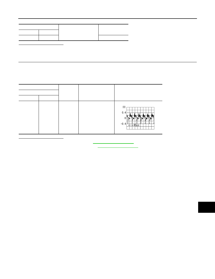
Check signal between AV control unit harness connector and ground.
Is inspection result normal?
YES
>> Replace AV control unit. Refer to
NO
>> Replace rear view camera. Refer to
.
AV control unit
Ground
Continuity
Connector
Terminal
M203
62
Not existed
(+)
(
−
)
Condition
Reference value
AV control unit
Connector
Terminal
M203
62
Ground
At rear view camera im-
age is displayed.
SKIB2251J
AV-114
< DTC/CIRCUIT DIAGNOSIS >
[WITHOUT NAVIGATION]
AUX IMAGE SIGNAL CIRCUIT
AUX IMAGE SIGNAL CIRCUIT
Description
INFOID:0000000005246826
• Transmits the image signal of AUX device from auxiliary input jacks to AV control unit.
• AV control unit transmits the image signal that is inputted to the front display unit.
Diagnosis Procedure
INFOID:0000000005246827
1.
CHECK CONTINUITY AUX IMAGE SIGNAL CIRCUIT (AUX INPUT JACKS AND AV CONTROL UNIT)
1.
Turn ignition switch OFF.
2.
Disconnect auxiliary input jacks connector and AV control unit connector.
3.
Check continuity between auxiliary input jacks harness connector and AV control unit harness connector.
4.
Check continuity between auxiliary input jacks harness connector and ground.
Is the inspection result normal?
YES
>> GO TO 2.
NO
>> Repair harness or connector.
2.
CHECK AUX IMAGE SIGNAL (AUX INPUT JACKS TO AV CONTROL UNIT)
1.
Connect auxiliary input jacks connector and AV control unit connector.
2.
Turn ignition switch ON.
3.
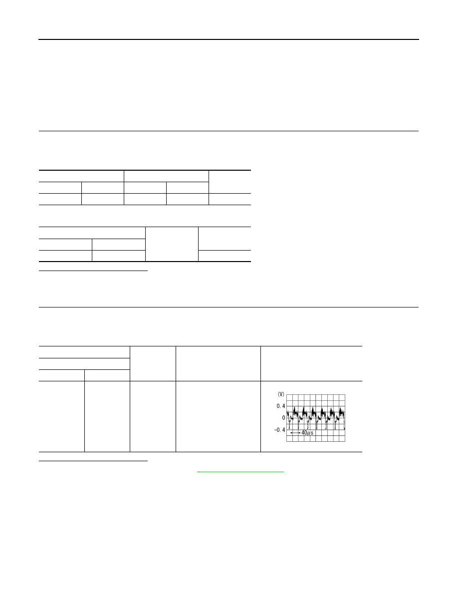
Check signal between auxiliary input jacks harness connector and ground.
Is the inspection result normal?
YES
>> Replace AV control unit. Refer to
NO
>> Check that there is no malfunction in the external device.
Auxiliary input jacks
AV control unit
Continuity
Connector
Terminal
Connector
Terminal
M196
7
M203
61
Existed
Auxiliary input jacks
Ground
Continuity
Connector
Terminal
M196
7
Not existed
(+)
(
−
)
Condition
Reference value
Auxiliary input jacks
Connector
Terminal
M196
7
Ground
At AUX image is displayed.
SKIB2251J
AV
DISK EJECT SIGNAL CIRCUIT
AV-115
< DTC/CIRCUIT DIAGNOSIS >
[WITHOUT NAVIGATION]
C
D
E
F
G
H
I
J
K
L
M
B
A
O
P
DISK EJECT SIGNAL CIRCUIT
Description
INFOID:0000000005246828
The disk eject signal is output to AV control unit when the eject switch of multifunction switch is pressed.
Diagnosis Procedure
INFOID:0000000005246829
1.
CHECK CONTINUITY DISK EJECT SIGNAL CIRCUIT
1.
Turn ignition switch OFF.
2.
Disconnect multifunction switch connector and AV control unit connector.
3.
Check continuity between multifunction switch harness connector and AV control unit harness connector.
4.
Check continuity between multifunction switch harness connector and ground.
Is the inspection result normal?
YES
>> GO TO 2.
NO
>> Repair harness or connector.
2.
CHECK AV CONTROL UNIT VOLTAGE
1.
Connect AV control unit connector.
2.
Turn ignition switch ON.
3.
Check voltage between AV control unit harness connector and ground.
Is the inspection result normal?
YES
>> Replace preset switch. Refer to
NO
>> Replace AV control unit. Refer to
Multifunction switch
AV control unit
Continuity
Connector
Terminal
Connector
Terminal
M72
14
M204
96
Existed
Multifunction switch
Ground
Continuity
Connector
Terminal
M72
14
Not existed
(+)
(
−
)
Reference value
(Approx.)
AV control unit
Connector
Terminal
M204
96
Ground
3.3 V
AV-116
< DTC/CIRCUIT DIAGNOSIS >
[WITHOUT NAVIGATION]
COMPOSITE IMAGE SIGNAL CIRCUIT
COMPOSITE IMAGE SIGNAL CIRCUIT
Description
INFOID:0000000005246834
AV control unit that inputs the camera image signal and AUX image signal transmits the composite image sig-
nal to the front display unit.
Diagnosis Procedure
INFOID:0000000005246835
1.
CHECK CONTINUITY COMPOSITE IMAGE SIGNAL CIRCUIT (AV CONTROL UNIT TO FRONT DISPLAY
UNIT)
1.
Turn ignition switch OFF.
2.
Disconnect AV control unit connector and front display unit connector.
3.
Check continuity between AV control unit harness connector and front display unit harness connector.
4.
Check continuity between AV control unit harness connector and ground.
Is inspection result normal?
YES
>> GO TO 2.
NO
>> Repair harness or connector.
2.
CHECK COMPOSITE IMAGE SIGNAL (AV CONTROL UNIT TO FRONT DISPLAY UNIT)
1.
Connect AV control unit connector and front display unit connector.
2.
Turn ignition switch ON.
3.
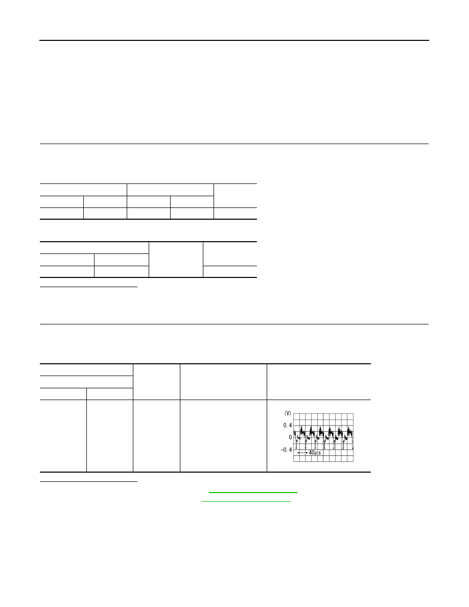
Check signal between AV control unit harness connector and ground.
Is inspection result normal?
YES
>> Replace front display unit. Refer to
.
NO
>> Replace AV control unit. Refer to
AV control unit
Front display unit
Continuity
Connector
Terminal
Connector
Terminal
M202
47
M194
15
Existed
AV control unit
Ground
Continuity
Connector
Terminal
M202
47
Not existed
(+)
(
−
)
Condition
Reference value
AV control unit
Connector
Terminal
M202
47
Ground
At rear view camera image
is displayed.
SKIB2251J
Нет комментариевНе стесняйтесь поделиться с нами вашим ценным мнением.
Текст