Infiniti FX35, FX50 (S51). Manual — part 86

AV
MICROPHONE SIGNAL CIRCUIT
AV-117
< DTC/CIRCUIT DIAGNOSIS >
[WITHOUT NAVIGATION]
C
D
E
F
G
H
I
J
K
L
M
B
A
O
P
MICROPHONE SIGNAL CIRCUIT
Description
INFOID:0000000005246836
Supply power from TEL adapter unit to microphone. The microphone transmits the sound/voice to the micro-
phone.
Diagnosis Procedure
INFOID:0000000005246837
1.
CHECK CONTINUITY BETWEEN TEL ADAPTER UNIT AND MICROPHONE CIRCUIT
1.
Turn ignition switch OFF.
2.
Disconnect TEL adapter unit connector and microphone connector.
3.
Check continuity between TEL adapter unit harness connector and microphone harness connector.
4.
Check continuity between TEL adapter unit harness connector and ground.
Is the inspection result normal?
YES
>> GO TO 2.
NO
>> Repair harness or connector.
2.
CHECK VOLTAGE MICROPHONE VCC
1.
Connect TEL adapter unit connector.
2.
Turn ignition switch ON.
3.
Check voltage between TEL adapter unit harness connector.
Is the inspection result normal?
YES
>> GO TO 3.
NO
>> Replace TEL adapter unit. Refer to
3.
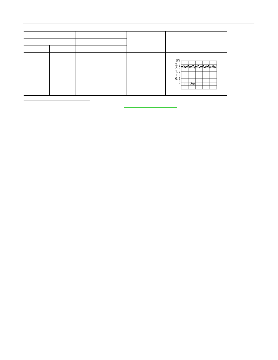
CHECK MICROPHONE SIGNAL
1.
Turn ignition switch OFF.
2.
Connect microphone connector.
3.
Turn ignition switch ON.
4.
Check signal between TEL adapter unit harness connector.
TEL adapter unit
Microphone
Continuity
Connector
Terminals
Connector
Terminals
B87
7
R17
1
Existed
8
2
29
4
TEL adapter unit
Ground
Continuity
Connector
Terminals
B87
7
Not existed
29
(+)
(
−
)
Voltage
(Approx.)
TEL adapter unit
TEL adapter unit
Connector
Terminal
Connector
Terminal
B87
29
B87
8
5.0 V
AV-118
< DTC/CIRCUIT DIAGNOSIS >
[WITHOUT NAVIGATION]
MICROPHONE SIGNAL CIRCUIT
Is the inspection result normal?
YES
>> Replace TEL adapter unit. Refer to
.
NO
>> Replace microphone. Refer to
(+)
(
−
)
Condition
Reference value
TEL adapter unit
TEL adapter unit
Connector
Terminal
Connector
Terminal
B87
7
B87
8
Give a voice.
PKIB5037J

AV
CONTROL SIGNAL CIRCUIT
AV-119
< DTC/CIRCUIT DIAGNOSIS >
[WITHOUT NAVIGATION]
C
D
E
F
G
H
I
J
K
L
M
B
A
O
P
CONTROL SIGNAL CIRCUIT
Description
INFOID:0000000005246838
TEL adapter unit identifies the vehicle model according to the control signal and performs the control.
Diagnosis Procedure
INFOID:0000000005246839
1.
CHECK CONTINUITY CONTROL SIGNAL CIRCUIT
1.
Turn ignition switch OFF.
2.
Disconnect TEL adapter unit connector.
3.
Check continuity between TEL adapter unit harness connector and ground.
Is the inspection result normal?
YES
>> Replace TEL adapter unit.
NO
>> Repair harness or connector.
TEL adapter unit
Ground
Continuity
Connector
Terminals
B87
20
Existed
23
24

AV-120
< DTC/CIRCUIT DIAGNOSIS >
[WITHOUT NAVIGATION]
MODE CHANGE SIGNAL CIRCUIT
MODE CHANGE SIGNAL CIRCUIT
Description
INFOID:0000000005530051
• AV control unit transmits the mode change signal to BOSE amp.
• Driver's Audio Stage controls the speaker's output characteristic by BOSE amp. so that the driver's seat is to
be the center of sounds.
Diagnosis Procedure
INFOID:0000000005530052
1.
CHECK CONTINUITY MODE CHANGE SIGNAL CIRCUIT
1.
Turn ignition switch OFF.
2.
Disconnect BOSE amp. connector and AV control unit connector.
3.
Check continuity between BOSE amp. harness connector and AV control unit harness connector.
4.
Check continuity between BOSE amp. harness connector and ground.
Is the inspection result normal?
YES
>> GO TO 2.
NO
>> Repair harness or connector.
2.
CHECK MODE CHANGE SIGNAL
1.
Connect BOSE amp. connector.
2.
Turn ignition switch ON.
3.
Check signal between BOSE amp. harness connector and ground.
Is the inspection result normal?
YES
>> Replace AV control unit. Refer to
NO
>> Replace BOSE amp. Refer to
.
BOSE amp.
AV control unit
Continuity
Connector
Terminal
Connector
Terminal
B41
17
M206
128
Existed
BOSE amp.
Ground
Continuity
Connector
Terminal
B41
17
Not existed
(+)
(
−
)
Condition
Voltage
(Approx.)
BOSE amp.
Connector
Terminal
B41
17
Ground
Driver's Audio Stage ON
0 V
Driver's Audio Stage OFF
8.5 V
Нет комментариевНе стесняйтесь поделиться с нами вашим ценным мнением.
Текст