Infiniti FX35, FX50 (S51). Manual — part 802
P006A, P0101, P010B MAF SENSOR
EC-749
< DTC/CIRCUIT DIAGNOSIS >
[VK50VE]
C
D
E
F
G
H
I
J
K
L
M
A
EC
N
P
O
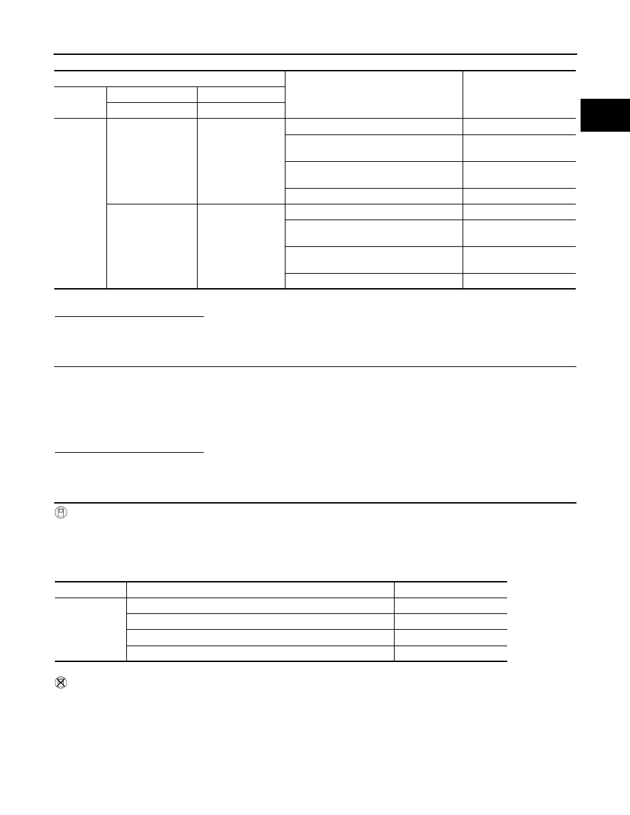
*: Check for linear voltage rise in response to engine being increased to about 4,000 rpm.
Is the inspection result normal?
YES
>> INSPECTION END
NO
>> GO TO 2.
2.
CHECK FOR THE CAUSE OF UNEVEN AIR FLOW THROUGH MASS AIR FLOW SENSOR
1.
Turn ignition switch OFF.
2.
Check for the cause of uneven air flow through mass air flow sensor. Refer to the following.
-
Crushed air ducts
-
Malfunctioning seal of air cleaner element
-
Uneven dirt of air cleaner element
-
Improper specification of intake air system parts
Is the inspection result normal?
YES
>> GO TO 4.
NO
>> GO TO 3.
3.
CHECK MASS AIR FLOW SENSOR-II
With CONSULT-III
1.
Repair or replace malfunctioning part.
2.
Start engine and warm it up to normal operating temperature.
3.
Connect CONSULT-III and select “DATA MONITOR” mode.
4.
Select “MAS A/F SE-B1” and “MAS A/F SE-B2”, and check the indication.
*: Check for linear voltage rise in response to engine being increased to about 4,000 rpm.
Without CONSULT-III
1.
Repair or replace malfunctioning part.
2.
Start engine and warm it up to normal operating temperature.
3.
Check the voltage between ECM harness connector terminals under the following conditions.
ECM
Condition
Voltage (V)
Connector
+
–
Terminal
Terminal
F110
47
[MAF sensor (bank 1)
signal]
42
Ignition switch ON (Engine stopped.)
Approx. 0.4
Idle (Engine is warmed-up to normal operat-
ing temperature.)
0.8 - 1.1
2,500 rpm (Engine is warmed-up to normal
operating temperature.)
1.3 - 1.6
Idle to about 4,000 rpm
0.8 - 1.1 to Approx. 2.4*
43
[MAF sensor (bank 2)
signal]
38
Ignition switch ON (Engine stopped.)
Approx. 0.4
Idle (Engine is warmed-up to normal operat-
ing temperature.)
0.8 - 1.1
2,500 rpm (Engine is warmed-up to normal
operating temperature.)
1.3 - 1.6
Idle to about 4,000 rpm
0.8 - 1.1 to Approx. 2.4*
Monitor item
Condition
Indication (V)
MAS A/F SE-B1
MAS A/F SE-B2
Ignition switch ON (Engine stopped.)
Approx. 0.4
Idle (Engine is warmed-up to normal operating temperature.)
0.8 - 1.1
2,500 rpm (Engine is warmed-up to normal operating temperature.)
1.3 - 1.6
Idle to about 4,000 rpm
0.8 - 1.1 to Approx. 2.4*
EC-750
< DTC/CIRCUIT DIAGNOSIS >
[VK50VE]
P006A, P0101, P010B MAF SENSOR
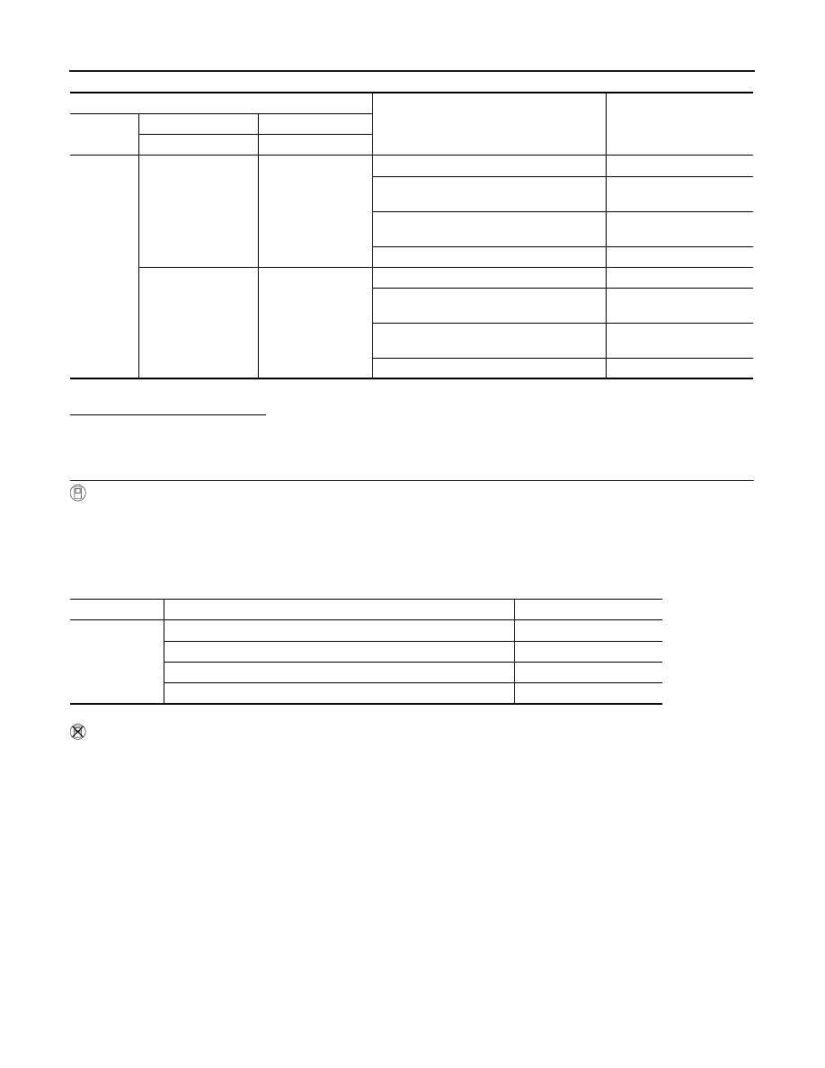
*: Check for linear voltage rise in response to engine being increased to about 4,000 rpm.
Is the inspection result normal?
YES
>> INSPECTION END
NO
>> GO TO 4.
4.
CHECK MASS AIR FLOW SENSOR-III
With CONSULT-III
1.
Turn ignition switch OFF.
2.
Disconnect mass air flow sensor harness connector and reconnect it again.
3.
Start engine and warm it up to normal operating temperature.
4.
Connect CONSULT-III and select “DATA MONITOR” mode.
5.
Select “MAS A/F SE-B1” and “MAS A/F SE-B2”, and check the indication.
*: Check for linear voltage rise in response to engine being increased to about 4,000 rpm.
Without CONSULT-III
1.
Turn ignition switch OFF.
2.
Disconnect mass air flow sensor harness connector and reconnect it again.
3.
Start engine and warm it up to normal operating temperature.
4.
Check the voltage between ECM harness connector terminals under the following conditions.
ECM
Condition
Voltage (V)
Connector
+
–
Terminal
Terminal
F110
47
[MAF sensor (bank 1)
signal]
42
Ignition switch ON (Engine stopped.)
Approx. 0.4
Idle (Engine is warmed-up to normal operat-
ing temperature.)
0.8 - 1.1
2,500 rpm (Engine is warmed-up to normal
operating temperature.)
1.3 - 1.6
Idle to about 4,000 rpm
0.8 - 1.1 to Approx. 2.4*
43
[MAF sensor (bank 2)
signal]
38
Ignition switch ON (Engine stopped.)
Approx. 0.4
Idle (Engine is warmed-up to normal operat-
ing temperature.)
0.8 - 1.1
2,500 rpm (Engine is warmed-up to normal
operating temperature.)
1.3 - 1.6
Idle to about 4,000 rpm
0.8 - 1.1 to Approx. 2.4*
Monitor item
Condition
Indication (V)
MAS A/F SE-B1
MAS A/F SE-B2
Ignition switch ON (Engine stopped.)
Approx. 0.4
Idle (Engine is warmed-up to normal operating temperature.)
0.8 - 1.1
2,500 rpm (Engine is warmed-up to normal operating temperature.)
1.3 - 1.6
Idle to about 4,000 rpm
0.8 - 1.1 to Approx. 2.4*
P006A, P0101, P010B MAF SENSOR
EC-751
< DTC/CIRCUIT DIAGNOSIS >
[VK50VE]
C
D
E
F
G
H
I
J
K
L
M
A
EC
N
P
O
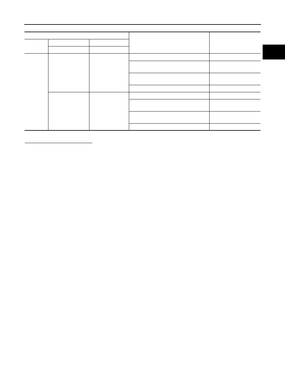
*: Check for linear voltage rise in response to engine being increased to about 4,000 rpm.
Is the inspection result normal?
YES
>> INSPECTION END
NO
>> Clean or replace malfunctioning mass air flow sensor.
ECM
Condition
Voltage (V)
Connector
+
–
Terminal
Terminal
F110
47
[MAF sensor (bank 1)
signal]
42
Ignition switch ON (Engine stopped.)
Approx. 0.4
Idle (Engine is warmed-up to normal operat-
ing temperature.)
0.8 - 1.1
2,500 rpm (Engine is warmed-up to normal
operating temperature.)
1.3 - 1.6
Idle to about 4,000 rpm
0.8 - 1.1 to Approx. 2.4*
43
[MAF sensor (bank 2)
signal]
38
Ignition switch ON (Engine stopped.)
Approx. 0.4
Idle (Engine is warmed-up to normal operat-
ing temperature.)
0.8 - 1.1
2,500 rpm (Engine is warmed-up to normal
operating temperature.)
1.3 - 1.6
Idle to about 4,000 rpm
0.8 - 1.1 to Approx. 2.4*
EC-752
< DTC/CIRCUIT DIAGNOSIS >
[VK50VE]
P0011, P0021 IVT CONTROL
P0011, P0021 IVT CONTROL
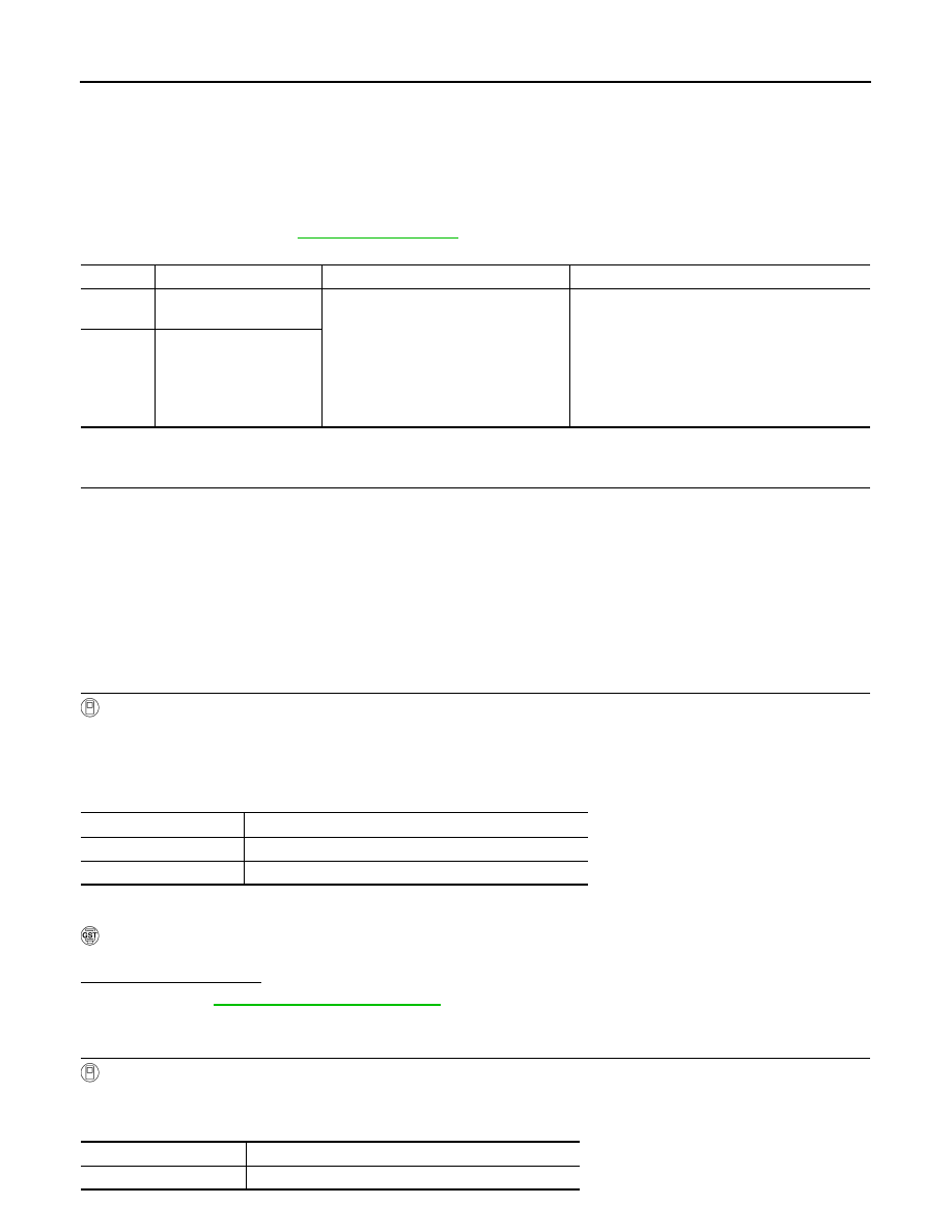
DTC Logic
INFOID:0000000005237232
DTC DETECTION LOGIC
NOTE:
If DTC P0011 or P0021 is displayed with DTC P0075 or P0081, first perform the trouble diagnosis for
DTC P0075, P0081. Refer to
.
DTC CONFIRMATION PROCEDURE
1.
PRECONDITIONING
If DTC Confirmation Procedure has been previously conducted, always perform the following procedure
before conducting the next test.
1.
Turn ignition switch OFF and wait at least 10 seconds.
2.
Turn ignition switch ON.
3.
Turn ignition switch OFF and wait at least 10 seconds.
TESTING CONDITION:
Before performing the following procedure, confirm that battery voltage is more than 11 V at idle.
>> GO TO 2.
2.
PERFORM DTC CONFIRMATION PROCEDURE-I
With CONSULT-III
1.
Turn ignition switch ON and select “DATA MONITOR” mode with CONSULT-III.
2.
Start engine and warm it up to the normal operating temperature.
3.
Maintain the following conditions for at least 6 consecutive seconds.
Hold the accelerator pedal as steady as possible.
4.
Let engine idle for 25 seconds.
5.
Check 1st trip DTC.
With GST
Follow the procedure “With CONSULT-III” above.
Is 1st trip DTC detected?
YES
>> Go to
NO
>> GO TO 3.
3.
PERFORM DTC CONFIRMATION PROCEDURE-II
With CONSULT-III
1.
Select “DATA MONITOR” mode with CONSULT-III.
2.
Maintain the following conditions for at least 20 consecutive seconds.
DTC No.
Trouble diagnosis name
Detecting condition
Possible cause
P0011
Intake valve timing control
performance (bank 1)
There is a gap between angle of target
and phase-control angle degree.
• Crankshaft position sensor
• Camshaft position sensor
• Intake valve timing control solenoid valve
• Accumulation of debris to the signal pick-up
portion of the camshaft
• Timing chain installation
• Foreign matter caught in the oil groove for in-
take valve timing control
P0021
Intake valve timing control
performance (bank 2)
ENG SPEED
Less than 2,000 rpm (A constant rotation is maintained.)
COOLAN TEMP/S
More than 70
°
C (158
°
F)
Selector lever
P or N position
ENG SPEED
1,500 - 3,175 rpm (A constant rotation is maintained.)
COOLAN TEMP/S
More than 70
°
C (158
°
F)
Нет комментариевНе стесняйтесь поделиться с нами вашим ценным мнением.
Текст