Infiniti FX35, FX50 (S51). Manual — part 801
P006A, P0101, P010B MAF SENSOR
EC-745
< DTC/CIRCUIT DIAGNOSIS >
[VK50VE]
C
D
E
F
G
H
I
J
K
L
M
A
EC
N
P
O
P006A, P0101, P010B MAF SENSOR
Description
INFOID:0000000005589031
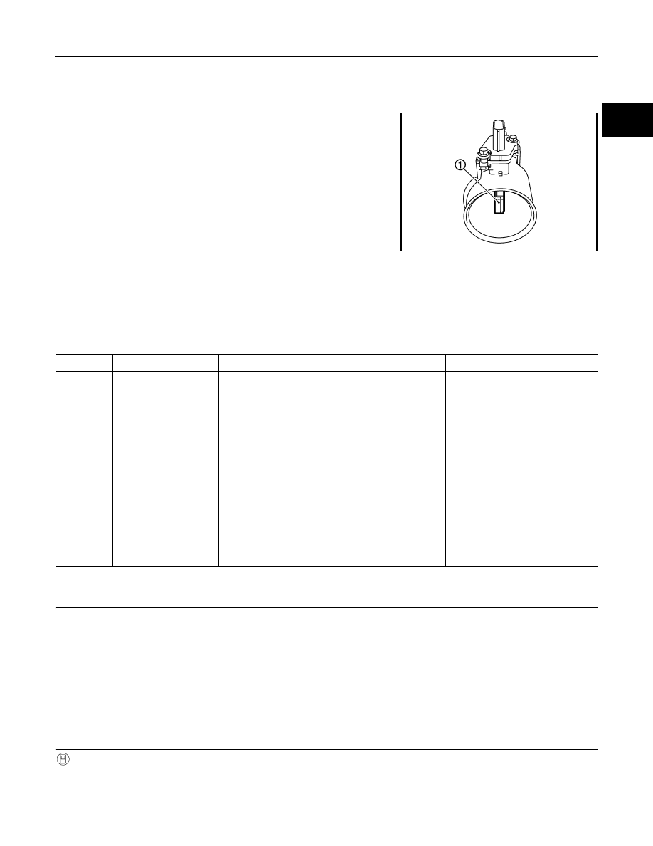
The mass air flow sensor (1) is placed in the stream of intake air. It
measures the intake flow rate by measuring a part of the entire
intake flow. The mass air flow sensor controls the temperature of the
hot wire to a certain amount. The heat generated by the hot wire is
reduced as the intake air flows around it. The greater air flow, the
greater the heat loss.
Therefore, the electric current supplied to hot wire is changed to
maintain the temperature of the hot wire as air flow increases. The
ECM detects the air flow by means of this current change.
DTC Logic
INFOID:0000000005589032
DTC DETECTION LOGIC
NOTE:
If DTC P006A, P0101 or P010B is displayed with other DTC, first perform the trouble diagnosis for
other DTC.
DTC CONFIRMATION PROCEDURE
1.
PRECONDITIONING
If DTC Confirmation Procedure has been previously conducted, always perform the following procedure
before conducting the next test.
1.
Turn ignition switch OFF and wait at least 10 seconds.
2.
Turn ignition switch ON.
3.
Turn ignition switch OFF and wait at least 10 seconds.
If engine will not start or stops soon, wait at least 10 seconds with engine stopped (Ignition switch ON) instead
of running engine at idle speed.
>> GO TO 2.
2.
PERFORM DTC CONFIRMATION PROCEDURE
With CONSULT-III
1.
Turn ignition switch ON and select “DATA MONITOR” mode with CONSULT-III.
2.
Start engine and warm it up to normal operating temperature.
3.
Accelerate the vehicle from 0 km/h (0 MPH) to 88 km/h (55 MPH) under the following conditions:
CAUTION:
PBIA9559J
DTC No.
Trouble diagnosis name
DTC detecting condition
Possible cause
P006A
Manifold pressure -
mass air flow correlation
A difference exceeding the specified value develops
between a value transmitted from the manifold absolute
pressure sensor to ECM and an estimated intake pres-
sure of intake manifold calculated by ECM, based on a
mass sir flow sensor signal.
• Harness or connectors
(The sensor circuit is open or
shorted.)
• Mass air flow sensor
• Manifold absolute pressure sen-
sor
• EVAP control system pressure
sensor
• Intake air leaks
• Intake air temperature sensor
P0101
Mass air flow sensor
(bank 1) circuit range/
performance
A difference exceeding the specified value develops
between a signal transmitted from the mass air flow
sensor (bank 1) to ECM and a signal transmitted from
the mass air flow sensor (bank 2) to ECM.
Mass air flow sensor (bank 1)
P010B
Mass air flow sensor
(bank 2) circuit range/
performance
Mass air flow sensor (bank 2)

EC-746
< DTC/CIRCUIT DIAGNOSIS >
[VK50VE]
P006A, P0101, P010B MAF SENSOR
Always drive at a safe speed.
NOTE:
• Accelerate with the accelerator pedal kept constant.
• The acceleration at engine speed 2,000 and 3,000 rpm allows easy diagnoses
CAUTION:
Always drive at a safe speed.
4.
Check 1st trip DTC.
Without CONSULT-III
1.
Start engine and warm it up to normal operating temperature.
2.
With selector lever in D position, accelerate the vehicle from 0 km/h (0 MPH) to 88 km/h (55 MPH) under
the following conditions:
NOTE:
• Accelerate with the accelerator pedal kept constant.
• The acceleration at engine speed 2,000 and 3,000 rpm allows easy diagnoses.
CAUTION:
Always drive at a safe speed.
3.
Check 1st trip DTC.
Is 1st trip DTC detected?
YES
>> Go to
NO
>> INSPECTION END
Diagnosis Procedure
INFOID:0000000005589033
1.
CHECK INTAKE SYSTEM
Check the following for connection.
• Air duct
• Vacuum hoses
• Intake air passage between air duct and intake manifold
Is the inspection result normal?
YES
>> GO TO 2.
NO
>> Reconnect the parts.
2.
CHECK GROUND CONNECTION
1.
Turn ignition switch OFF.
2.
Check ground connection M95. Refer to Ground Inspection in
Is the inspection result normal?
YES
>> GO TO 3.
NO
>> Repair or replace ground connection.
3.
CHECK MASS AIR FLOW SENSOR POWER SUPPLY CIRCUIT
1.
Disconnect mass air flow sensor harness connector.
2.
Turn ignition switch ON.
3.
Check the voltage between mass air flow sensor harness connector and ground.
ACCEL SEN 1
1.4 – 2.0 V
Selector lever
D position
Accelerator pedal position sensor 1
Ground
Voltage (V)
Connector
Terminal
E112 (Whthout ICC)
3
Ground
1.4 – 2.0
E116 (With ICC)

P006A, P0101, P010B MAF SENSOR
EC-747
< DTC/CIRCUIT DIAGNOSIS >
[VK50VE]
C
D
E
F
G
H
I
J
K
L
M
A
EC
N
P
O
Is the inspection result normal?
YES
>> GO TO 5.
NO
>> GO TO 4.
4.
DETECT MALFUNCTIONING PART
Check the following.
• Harness connectors E106, M6
• Harness connectors M116, F103
• Harness for open or short between mass air flow sensor and ECM
• Harness for open or short between mass air flow sensor and IPDM E/R
>> Repair open circuit, short to ground or short to power in harness or connectors.
5.
CHECK MASS AIR FLOW SENSOR GROUND CIRCUIT FOR OPEN AND SHORT
1.
Turn ignition switch OFF.
2.
Disconnect ECM harness connector.
3.
Check the continuity between mass air flow sensor harness connector and ECM harness connector.
4.
Also check harness for short to ground and short to power.
Is the inspection result normal?
YES
>> GO TO 6.
NO
>> Repair open circuit, short to ground or short to power in harness or connectors.
6.
CHECK MASS AIR FLOW SENSOR INPUT SIGNAL CIRCUIT FOR OPEN AND SHORT
1.
Check the continuity between mass air flow sensor harness connector and ECM harness connector.
2.
Also check harness for short to ground and short to power.
Is the inspection result normal?
YES
>> GO TO 7.
NO
>> Repair open circuit, short to ground or short to power in harness or connectors.
7.
CHECK MANIFOLD ABSOLUTE PRESSURE SENSOR
Check manifold absolute pressure sensor. Refer to
EC-780, "Component Inspection"
.
Is the inspection result normal?
YES
>> GO TO 8.
NO
>> Replace manifold absolute pressure sensor.
8.
CHECK INTAKE AIR TEMPERATURE SENSOR
Check intake air temperature sensor. Refer to
EC-802, "Component Inspection"
.
Is the inspection result normal?
DTC
Mass air flow sensor
Ground
Voltage
Bank
Connector
Terminal
P006A, P0101
1
F86
5
Ground
Battery voltage
P006A, P010B
2
F85
5
DTC
Mass air flow sensor
ECM
Continuity
Bank
Connector
Terminal
Connector
Terminal
P006A, P0101
1
F86
4
F110
42
Existed
P006A, P010B
2
F85
4
38
DTC
Mass air flow sensor
ECM
Continuity
Bank
Connector
Terminal
Connector
Terminal
P006A, P0101
1
F86
3
F110
47
Existed
P006A, P010B
2
F85
3
43
EC-748
< DTC/CIRCUIT DIAGNOSIS >
[VK50VE]
P006A, P0101, P010B MAF SENSOR
YES
>> GO TO 9.
NO
>> Replace mass air flow sensor (with intake air temperature sensor).
9.
CHECK EVAP CONTROL SYSTEM PRESSURE SENSOR
EC-917, "Component Inspection"
Is the inspection result normal?
YES-1 (Only DTC P006A is detected)>>GO TO 10.
YES-2 (DTC P006A and P0101 are detected)>>GO TO 11.
YES-3 (DTC P006A and P010B are detected)>>GO TO 12.
NO
>> Replace EVAP control system pressure sensor.
10.
CHECK MASS AIR FLOW SENSOR
EC-748, "Component Inspection"
Is the inspection result normal?
YES
>> GO TO 13.
NO
>> Replace mass air flow sensor (bank 1) and (bank 2).
11.
CHECK MASS AIR FLOW SENSOR (BANK 1)
Check mass air flow sensor (bank 1). Refer to
EC-748, "Component Inspection"
.
Is the inspection result normal?
YES
>> GO TO 13.
NO
>> Replace mass air flow sensor (bank 1).
12.
CHECK MASS AIR FLOW SENSOR (BANK 2)
Check mass air flow sensor (bank 2). Refer to
EC-748, "Component Inspection"
.
Is the inspection result normal?
YES
>> GO TO 13.
NO
>> Replace mass air flow sensor (bank 2).
13.
CHECK INTERMITTENT INCIDENT
GI-36, "Intermittent Incident"
>> INSPECTION END
Component Inspection
INFOID:0000000005589034
1.
CHECK MASS AIR FLOW SENSOR-I
With CONSULT-III
1.
Turn ignition switch OFF.
2.
Reconnect all harness connectors disconnected.
3.
Start engine and warm it up to normal operating temperature.
4.
Connect CONSULT-III and select “DATA MONITOR” mode.
5.
Select “MAS A/F SE-B1” and “MAS A/F SE-B2”, and check the indication.
*: Check for linear voltage rise in response to engine being increased to about 4,000 rpm.
Without CONSULT-III
1.
Turn ignition switch OFF.
2.
Reconnect all harness connectors disconnected.
3.
Start engine and warm it up to normal operating temperature.
4.
Check the voltage between ECM harness connector terminals under the following conditions.
Monitor item
Condition
Indication (V)
MAS A/F SE-B1
MAS A/F SE-B2
Ignition switch ON (Engine stopped.)
Approx. 0.4
Idle (Engine is warmed-up to normal operating temperature.)
0.8 - 1.1
2,500 rpm (Engine is warmed-up to normal operating temperature.)
1.3 - 1.6
Idle to about 4,000 rpm
0.8 - 1.1 to Approx. 2.4*
Нет комментариевНе стесняйтесь поделиться с нами вашим ценным мнением.
Текст