Infiniti FX35, FX50 (S51). Manual — part 1443
PCS-130
< PRECAUTION >
[POWER DISTRIBUTION SYSTEM]
PRECAUTIONS
5.
When the repair work is completed, re-connect both battery cables. With the brake pedal released, turn
the push-button ignition switch from ACC position to ON position, then to LOCK position. (The steering
wheel will lock when the push-button ignition switch is turned to LOCK position.)
6.
Perform self-diagnosis check of all control units using CONSULT-III.

PCS
PUSH-BUTTON IGNITION SWITCH DOES NOT OPERATE
PCS-131
< SYMPTOM DIAGNOSIS >
[POWER DISTRIBUTION SYSTEM]
C
D
E
F
G
H
I
J
K
L
B
A
O
P
N
SYMPTOM DIAGNOSIS
PUSH-BUTTON IGNITION SWITCH DOES NOT OPERATE
Description
INFOID:0000000005240717
Check that vehicle is under the condition shown in “Conditions of vehicle” before starting diagnosis, and check
each symptom.
NOTE:
The engine start function, door lock function, power distribution system and NATS-IVIS/NVIS in the Intelligent
Key system are closely related to each other regarding control. The vehicle security function can operate only
when the door lock and power distribution system are operating normally.
Conditions of Vehicle (Operating Conditions)
• “ENGINE START BY I-KEY” in “WORK SUPPORT” is ON when setting on CONSULT-III.
• Intelligent Key is not inserted in key slot.
• One or more of Intelligent Keys with registered Intelligent Key ID is in the vehicle.
Diagnosis Procedure
INFOID:0000000005240718
1.
CHECK DOOR LOCK FUNCTION
Lock/unlock door with door request switch.
Refer to
DLK-19, "DOOR LOCK FUNCTION : System Description"
Is the operation normal?
YES
>> GO TO 2.
NO
>> Check door lock function. Refer to
DLK-197, "DRIVER SIDE : Diagnosis Procedure"
.
2.
PERFORM WORK SUPPORT
Perform “INSIDE ANT DIAGNOSIS” on “Work Support” of “INTELIGENT KEY”.
Refer to
SEC-25, "INTELLIGENT KEY : CONSULT-III Function (BCM - INTELLIGENT KEY)"
>> GO TO 3.
3.
PERFORM SELF DIAGNOSTIC RESULT
Perform Self Diagnostic result of “INTELIGENT KEY”.
Refer to
SEC-25, "INTELLIGENT KEY : CONSULT-III Function (BCM - INTELLIGENT KEY)"
Is DTC detected?
YES
>> Refer to
(console), refer
to
(luggage room).
NO
>> GO TO 4.
4.
CHECK PUSH-BUTTON IGNITION SWITCH
Check push-button ignition switch.
Refer to
PCS-64, "Component Function Check"
Is the inspection normal?
YES
>> GO TO 5.
NO
>> Repair or replace malfunctioning parts.
5.
CONFIRM THE OPERATION
Confirm the operation again.
Is the inspection normal?
YES
>> Check intermittent incident. Refer to
GI-36, "Intermittent Incident"
.
NO
>> GO TO 1.

PCS-132
< SYMPTOM DIAGNOSIS >
[POWER DISTRIBUTION SYSTEM]
PUSH-BUTTON IGNITION SWITCH POSITION INDICATOR DOES NOT ILLUMI-
NATE
PUSH-BUTTON IGNITION SWITCH POSITION INDICATOR DOES NOT IL-
LUMINATE
Diagnosis Procedure
INFOID:0000000005240719
1.
CHECK PUSH-BUTTON IGNITION SWITCH OPERATION
Check push-button ignition switch operation.
Refer to
Is the inspection result normal?
YES
>> GO TO 2.
NO
>> Refer to
PCS-64, "Component Function Check"
2.
CHECK PUSH-BUTTON IGNITION SWITCH INDICATOR
Check push-button ignition switch indicator.
Refer to
PCS-67, "Component Function Check"
Is the inspection result normal?
YES
>> GO TO 3.
NO
>> Repair or replace the malfunctioning parts.
3.
CONFIRM THE OPERATION
Confirm the operation again.
Is the result normal?
YES
>> Check intermittent incident. Refer to
GI-36, "Intermittent Incident"
.
NO
>> GO TO 1.
PCS
PUSH BUTTON IGNITION SWITCH
PCS-133
< REMOVAL AND INSTALLATION >
[POWER DISTRIBUTION SYSTEM]
C
D
E
F
G
H
I
J
K
L
B
A
O
P
N
REMOVAL AND INSTALLATION
PUSH BUTTON IGNITION SWITCH
Removal and Installation
INFOID:0000000005240722
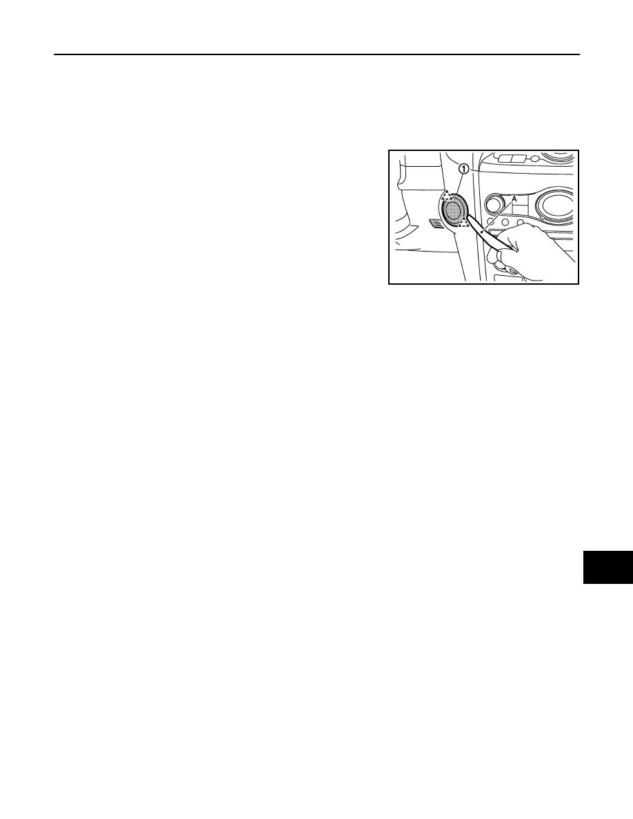
REMOVAL
Remove the push-button ignition switch fixing pawl using a remover
tool (A), and then remove push-button ignition switch (1).
INSTALLATION
Install in the reverse order of removal.
JMMIA0024ZZ
Нет комментариевНе стесняйтесь поделиться с нами вашим ценным мнением.
Текст