Infiniti FX35, FX50 (S51). Manual — part 1444
PG
PG-1
ELECTRICAL & POWER CONTROL
C
D
E
F
G
H
I
J
K
L
B
SECTION
PG
A
O
P
N
CONTENTS
POWER SUPPLY, GROUND & CIRCUIT ELEMENTS
POWER SUPPLY & GROUND CIRCUIT
BASIC INSPECTION . . . . . . . . .
BATTERY . . . . . . . . . . . . . . .
How to Handle Battery . . . . . . . . . . . ..
Work Flow . . . . . . . . . . . . . . . .....
DTC/CIRCUIT DIAGNOSIS . . . . . . ..
POWER SUPPLY ROUTING CIRCUIT . . . ...
Wiring Diagram - BATTERY POWER SUPPLY - . ..
Wiring Diagram - BATTERY POWER SUPPLY
FUSIBLE LINK No. L - . . . . . . . . . . .
Wiring Diagram - BATTERY POWER SUPPLY
FUSE No. 6 - . . . . . . . . . . . . . . ...
Wiring Diagram - BATTERY POWER SUPPLY
FUSE No. 7 - . . . . . . . . . . . . . . ...
Wiring Diagram - BATTERY POWER SUPPLY
FUSE No. 10 - . . . . . . . . . . . . . . .
Wiring Diagram - BATTERY POWER SUPPLY
FUSE No. 11 - . . . . . . . . . . . . . . .
Wiring Diagram - BATTERY POWER SUPPLY
FUSE No. 34 - . . . . . . . . . . . . . . .
Wiring Diagram - BATTERY POWER SUPPLY
FUSE No. 50 - . . . . . . . . . . . . . . .
Wiring Diagram - BATTERY POWER SUPPLY
FUSE No. 53 - . . . . . . . . . . . . . . .
Wiring Diagram - ACCESSORY POWER SUP-
PLY - . . . . . . . . . . . . . . . . . ...
Wiring Diagram - ACCESSORY POWER SUP-
PLY FUSE No. 19 - . . . . . . . . . . . . .
Wiring Diagram - IGNITION POWER SUPPLY - .
Wiring Diagram - IGNITION POWER SUPPLY
FUSE No. 3 - . . . . . . . . . . . . . . ...
Wiring Diagram - IGNITION POWER SUPPLY
FUSE No. 4 - . . . . . . . . . . . . . . .
Wiring Diagram - IGNITION POWER SUPPLY
FUSE No. 44 - . . . . . . . . . . . . . ...
Wiring Diagram - IGNITION POWER SUPPLY
FUSE No. 45 - . . . . . . . . . . . . . ...
Wiring Diagram - IGNITION POWER SUPPLY
FUSE No. 46 - . . . . . . . . . . . . . ...
Fuse . . . . . . . . . . . . . . . . . ...
Fusible Link . . . . . . . . . . . . . . ...
Circuit Breaker . . . . . . . . . . . . . ...
OPTION HARNESS . . . . . . . . . .
Wiring Diagram - OPTION HARNESS - . . . .
HARNESS LAYOUT . . . . . . . . . ...
How To Read Harness Layout . . . . . . . ..
Outline . . . . . . . . . . . . . . . . ...
Main Harness . . . . . . . . . . . . . .
Engine Room Harness . . . . . . . . . . ..
Engine Control Harness (VQ35HR) . . . . . ...
Engine Control Harness (VK50VE) . . . . . ...
Body Harness . . . . . . . . . . . . . .
Body No. 2 Harness . . . . . . . . . . . ..
Room Lamp Harness . . . . . . . . . . . .
Front Door Harness (LH Side) . . . . . . . ...
Front Door Harness (RH Side) . . . . . . . ..
Rear Door Harness (LH Side) . . . . . . . ...
Rear Door Harness (RH Side) . . . . . . . ...
Back Door Harness . . . . . . . . . . . ...
HARNESS CONNECTOR . . . . . . . ...
Description . . . . . . . . . . . . . . . .
STANDARDIZED RELAY . . . . . . . ...
Description . . . . . . . . . . . . . . . .
FUSE BLOCK - JUNCTION BOX (J/B) . . ..
Fuse, Connector and Terminal Arrangement . .
FUSE, FUSIBLE LINK AND RELAY BOX . ..
Fuse and Fusible Link Arrangement . . . . . ..
IPDM E/R (INTELLIGENT POWER DISTRI-
BUTION MODULE ENGINE ROOM) . . . ..
Fuse, Connector and Terminal Arrangement . .
PG-2
PRECAUTIONS . . . . . . . . . . . ...
Precaution for Procedure without Cowl Top Cover ..
PREPARATION . . . . . . . . . . ..
PREPARATION . . . . . . . . . . . ...
Special Service Tools . . . . . . . . . . .
REMOVAL AND INSTALLATION . . . ..
BATTERY . . . . . . . . . . . . . .
Exploded View . . . . . . . . . . . . . ..
Removal and Installation . . . . . . . . . ...
BATTERY TERMINAL WITH FUSIBLE LINK ..
Exploded View . . . . . . . . . . . . . ..
Removal and Installation . . . . . . . . . ...
SERVICE DATA AND SPECIFICATIONS
(SDS) . . . . . . . . . . . . . . .
SERVICE DATA AND SPECIFICATIONS
(SDS) . . . . . . . . . . . . . . . .
PG
BATTERY
PG-3
< BASIC INSPECTION >
[POWER SUPPLY & GROUND CIRCUIT]
C
D
E
F
G
H
I
J
K
L
B
A
O
P
N
BASIC INSPECTION
BATTERY
How to Handle Battery
INFOID:0000000005240733
CAUTION:
• If it becomes necessary to start the engine with a booster battery and jumper cables, use a 12-volt
booster battery.
• After connecting battery cables, ensure that they are tightly clamped to battery terminals for good
contact.
• Never add distilled water through the hole used to check specific gravity.
METHODS OF PREVENTING OVER-DISCHARGE
The following precautions must be taken to prevent over-discharging a battery.
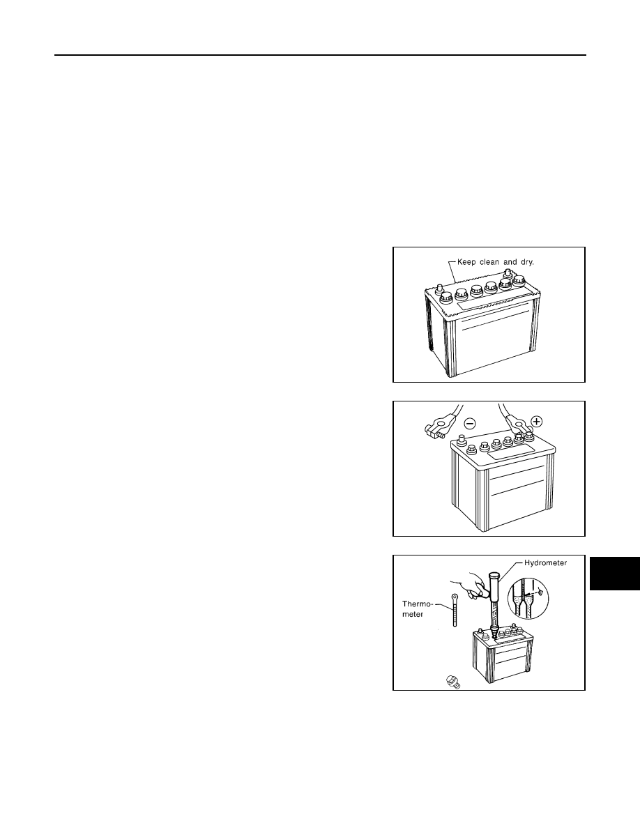
• The battery surface (particularly its top) should always be kept
clean and dry.
• The terminal connections should be clean and tight.
• At every routine maintenance, check the electrolyte level.
This also applies to batteries designated as “low maintenance” and
“maintenance-free”.
• When the vehicle is not going to be used over a long period of
time, disconnect the battery cable from the negative terminal. (If
the vehicle has an extended storage switch, turn it off.)
• Check the charge condition of the battery.
Periodically check the specific gravity of the electrolyte. Keep a
close check on charge condition to prevent over-discharge.
CHECKING ELECTROLYTE LEVEL
WARNING:
Never allow battery fluid to come in contact with skin, eyes, fabrics, or painted surfaces. After touch-
ing a battery, never touch or rub your eyes until you have thoroughly washed your hands. If acid con-
tacts eyes, skin or clothing, immediately flush with water for 15 minutes and seek medical attention.
MEL040F
ELA0349D
MEL042F
PG-4
< BASIC INSPECTION >
[POWER SUPPLY & GROUND CIRCUIT]
BATTERY
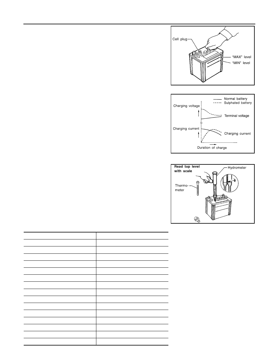
• Remove the cell plug using a suitable tool.
• Add distilled water up to the MAX level.
Sulphation
A battery will be completely discharged if it is left unattended
for a long time and the specific gravity will become less than
1.100. This may result in sulphation on the cell plates.
To determine if a battery has been “sulphated”, note its voltage
and current when charging it. As shown in the figure, less cur-
rent and higher voltage are observed in the initial stage of
charging sulphated batteries.
A sulphated battery may sometimes be brought back into ser-
vice by means of a long, slow charge, 12 hours or more, fol-
lowed by a battery capacity test.
SPECIFIC GRAVITY CHECK
1.
Read hydrometer and thermometer indications at eye level.
2.
Use the chart below to correct your hydrometer reading accord-
ing to electrolyte temperature.
Hydrometer Temperature Correction
MEL043F
PKIA2353E
MEL042FA
Battery electrolyte temperature [
°
C (
°
F)]
Add to specific gravity reading
71 (160)
0.032
66 (150)
0.028
60 (140)
0.024
54 (130)
0.020
49 (120)
0.016
43 (110)
0.012
38 (100)
0.008
32 (90)
0.004
27 (80)
0
21 (70)
−
0.004
16 (60)
−
0.008
10 (50)
−
0.012
4 (40)
−
0.016
−
1 (30)
−
0.020
−
7 (20)
−
0.024
Нет комментариевНе стесняйтесь поделиться с нами вашим ценным мнением.
Текст