Infiniti FX35, FX50 (S51). Manual — part 882
P1608 VVEL SENSOR POWER SUPPLY
EC-1069
< DTC/CIRCUIT DIAGNOSIS >
[VK50VE]
C
D
E
F
G
H
I
J
K
L
M
A
EC
N
P
O
>> GO TO 2.
2.
PERFORM IDLE AIR VOLUME LEARNING
EC-582, "IDLE AIR VOLUME LEARNING : Special Repair Requirement"
>> END

EC-1070
< DTC/CIRCUIT DIAGNOSIS >
[VK50VE]
P1715 INPUT SPEED SENSOR
P1715 INPUT SPEED SENSOR
Description
INFOID:0000000005237567
ECM receives input speed sensor signal from TCM by the CAN communication line. ECM uses this signal for
engine control.
DTC Logic
INFOID:0000000005237568
DTC DETECTION LOGIC
NOTE:
• If DTC P1715 is displayed with DTC UXXXX, first perform the trouble diagnosis for DTC UXXXX.
• If DTC P1715 is displayed with DTC P0335, first perform the trouble diagnosis for DTC P0335. Refer
• If DTC P1715 is displayed with DTC P0340, first perform the trouble diagnosis for DTC P0340. Refer
• If DTC P1715 is displayed with DTC P0605, first perform the trouble diagnosis for DTC P0605. Refer
• If DTC P1715 is displayed with DTC P0607, first perform the trouble diagnosis for DTC P0607. Refer
Diagnosis Procedure
INFOID:0000000005237569
1.
CHECK DTC WITH TCM
Check DTC with TCM. Refer to
TM-242, "Diagnosis Description"
Is the inspection result normal?
YES
>> GO TO 2.
NO
>> Perform Diagnosis Procedure corresponding to DTC indicated.
2.
REPLACE TCM
Replace TCM.
>> INSPECTION END
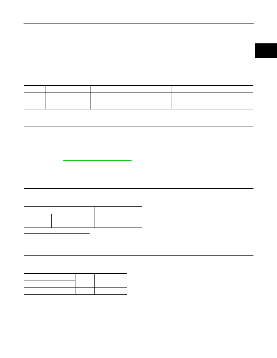
DTC No.
Trouble diagnosis name
DTC detecting condition
Possible cause
P1715
Input speed sensor
(TCM output)
Input speed sensor signal is different from the
theoretical value calculated by ECM from output
speed sensor signal and engine rpm signal.
• Harness or connectors
(The CAN communication line is open or
shorted)
(Input speed sensor circuit is open or
shorted)
• TCM
P1805 BRAKE SWITCH
EC-1071
< DTC/CIRCUIT DIAGNOSIS >
[VK50VE]
C
D
E
F
G
H
I
J
K
L
M
A
EC
N
P
O
P1805 BRAKE SWITCH
Description
INFOID:0000000005237570
Brake switch signal is applied to the ECM through the stop lamp switch when the brake pedal is depressed.
This signal is used mainly to decrease the engine speed when the vehicle is being driven.
DTC Logic
INFOID:0000000005237571
DTC DETECTION LOGIC
DTC CONFIRMATION PROCEDURE
1.
PERFORM DTC CONFIRMATION PROCEDURE
1.
Turn ignition switch ON.
2.
Fully depress the brake pedal for at least 5 seconds.
3.
Erase the DTC.
4.
Check 1st trip DTC.
Is 1st trip DTC detected?
YES
>> Go to
EC-1071, "Diagnosis Procedure"
NO
>> INSPECTION END
Diagnosis Procedure
INFOID:0000000005237572
1.
CHECK STOP LAMP SWITCH CIRCUIT
1.
Turn ignition switch OFF.
2.
Check for stop lamp illumination under the following conditions.
Is the inspection result normal?
YES
>> GO TO 4.
NO
>> GO TO 2.
2.
CHECK STOP LAMP SWITCH POWER SUPPLY CIRCUIT
1.
Disconnect stop lamp switch harness connector.
2.
Check the voltage between stop lamp switch harness connector and ground.
Is the inspection result normal?
YES
>> GO TO 4.
NO
>> GO TO 3.
3.
DETECT MALFUNCTIONING PART
Check the following.
• Fuse block (J/B) connector E103
• 10 A fuse (No. 7)
• Harness for open or short between stop lamp switch and battery
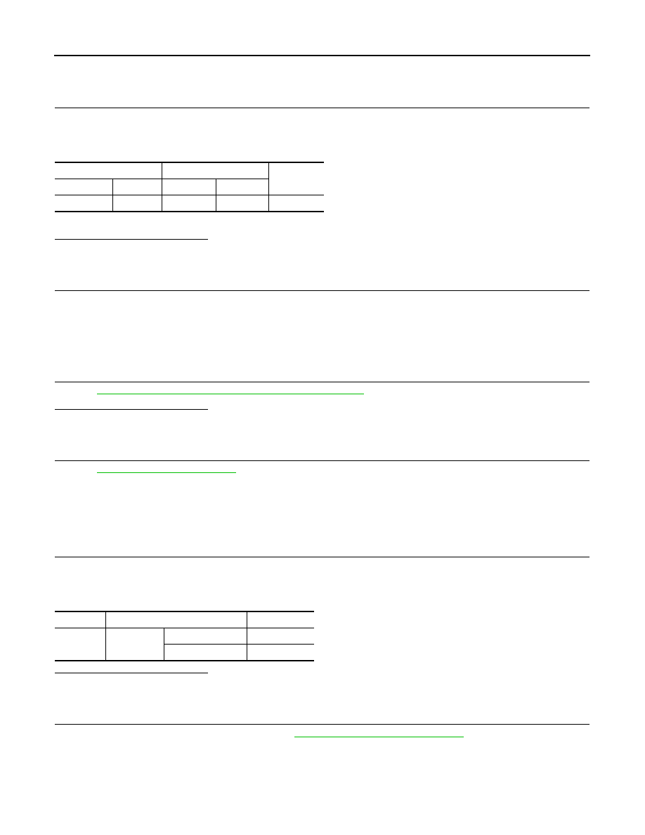
DTC No.
Trouble diagnosis name
DTC detecting condition
Possible cause
P1805
Brake switch
A brake switch signal is not sent to ECM for
extremely long time while the vehicle is being
driven.
• Harness or connectors
(Stop lamp switch circuit is open or shorted.)
• Stop lamp switch
Condition
Stop lamp
Brake pedal
Fully released
Not illuminated
Slightly depressed
Illuminated
Stop lamp switch
Ground
Voltage
Connector
Terminal
E110
3
Ground
Battery voltage
EC-1072
< DTC/CIRCUIT DIAGNOSIS >
[VK50VE]
P1805 BRAKE SWITCH
>> Repair open circuit, short to ground or short to power in harness or connectors.
4.
CHECK STOP LAMP SWITCH INPUT SIGNAL CIRCUIT FOR OPEN AND SHORT
1.
Disconnect stop lamp switch harness connector.
2.
Disconnect ECM harness connector.
3.
Check the continuity between stop lamp switch harness connector and ECM harness connector.
4.
Also check harness for short to ground and short to power.
Is the inspection result normal?
YES
>> GO TO 6.
NO
>> GO TO 5.
5.
DETECT MALFUNCTIONING PART
Check the following.
• Fuse block (J/B) connector E103, M2
• Harness for open or short between ECM and stop lamp switch
>> Repair open circuit, short to ground or short to power in harness or connectors.
6.
CHECK STOP LAMP SWITCH
EC-1072, "Component Inspection (Stop Lamp Switch)"
Is the inspection result normal?
YES
>> GO TO 7.
NO
>> Replace stop lamp switch.
7.
CHECK INTERMITTENT INCIDENT
GI-36, "Intermittent Incident"
>> INSPECTION END
Component Inspection (Stop Lamp Switch)
INFOID:0000000005237573
1.
CHECK STOP LAMP SWITCH-I
1.
Turn ignition switch OFF.
2.
Disconnect stop lamp switch harness connector.
3.
Check the continuity between stop lamp switch terminals under the following conditions.
Is the inspection result normal?
YES
>> INSPECTION END
NO
>> GO TO 2.
2.
CHECK STOP LAMP SWITCH-II
1.
Adjust stop lamp switch installation. Refer to
BR-7, "Inspection and Adjustment"
2.
Check the continuity between stop lamp switch terminals under the following conditions.
Stop lamp switch
ECM
Continuity
Connector
Terminal
Connector
Terminal
E110
4
M160
110
Existed
Terminals
Condition
Continuity
3 and 4
Brake pedal
Fully released
Not existed
Slightly depressed
Existed
Нет комментариевНе стесняйтесь поделиться с нами вашим ценным мнением.
Текст