Infiniti FX35, FX50 (S51). Manual — part 881
P1607 VVEL CONTROL MODULE
EC-1065
< DTC/CIRCUIT DIAGNOSIS >
[VK50VE]
C
D
E
F
G
H
I
J
K
L
M
A
EC
N
P
O
P1607 VVEL CONTROL MODULE
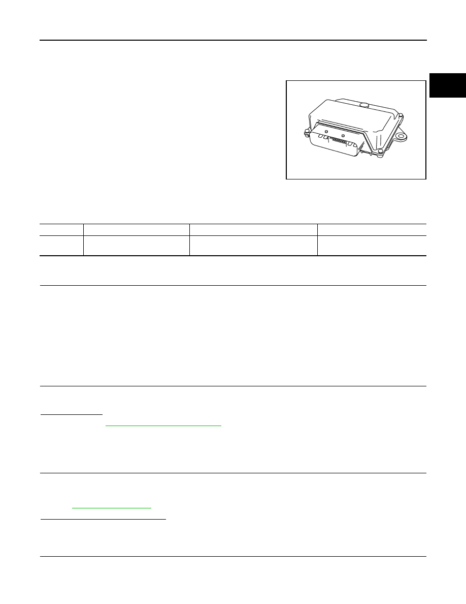
Description
INFOID:0000000005237561
The VVEL control module consists of a microcomputer and connec-
tors for signal input and output and for power supply. The VVEL con-
trol module controls VVEL system.
DTC Logic
INFOID:0000000005237562
DTC DETECTION LOGIC
DTC CONFIRMATION PROCEDURE
1.
PRECONDITIONING
If DTC Confirmation Procedure has been previously conducted, always perform the following procedure
before conducting the next test.
1.
Turn ignition switch OFF and wait at least 10 seconds.
2.
Turn ignition switch ON.
3.
Turn ignition switch OFF and wait at least 10 seconds.
TESTING CONDITION:
Before performing the following procedure, confirm that battery voltage is more than 10 V at idle.
>> GO TO 2.
2.
PERFORM DTC CONFIRMATION PROCEDURE
1.
Start engine and let it idle for at least 1 second.
2.
Check DTC.
Is DTC detected?
YES
>> Go to
EC-1065, "Diagnosis Procedure"
NO
>> INSPECTION END
Diagnosis Procedure
INFOID:0000000005237563
1.
PERFORM DTC CONFIRMATION PROCEDURE
1.
Turn ignition switch ON.
2.
Erase DTC.
3.
Perform DTC Confirmation Procedure.
See
.
Is the DTC P1607 displayed again?
YES
>> GO TO 2.
NO
>> INSPECTION END
2.
REPLACE VVEL CONTROL MODULE
1.
Replace VVEL control module.
JMBIA0879ZZ
DTC No.
Trouble diagnosis name
DTC detecting condition
Possible cause
P1607
VVEL control module circuit
• The internal circuit of the VVEL control
module is malfunctioning.
• VVEL control module
EC-1066
< DTC/CIRCUIT DIAGNOSIS >
[VK50VE]
P1607 VVEL CONTROL MODULE
2.
Go to
EC-579, "ADDITIONAL SERVICE WHEN REPLACING CONTROL UNIT (VVEL CONTROL MOD-
ULE) : Special Repair Requirement"
>> INSPECTION END
P1608 VVEL SENSOR POWER SUPPLY
EC-1067
< DTC/CIRCUIT DIAGNOSIS >
[VK50VE]
C
D
E
F
G
H
I
J
K
L
M
A
EC
N
P
O
P1608 VVEL SENSOR POWER SUPPLY
DTC Logic
INFOID:0000000005237564
DTC DETECTION LOGIC
DTC CONFIRMATION PROCEDURE
1.
PRECONDITIONING
If DTC Confirmation Procedure has been previously conducted, always perform the following procedure
before conducting the next test.
1.
Turn ignition switch OFF and wait at least 10 seconds.
2.
Turn ignition switch ON.
3.
Turn ignition switch OFF and wait at least 10 seconds.
TESTING CONDITION:
Before performing the following procedure, confirm that battery voltage is more than 10 V at idle.
>> GO TO 2.
2.
PERFORM DTC CONFIRMATION PROCEDURE
1.
Turn ignition switch ON and wait at least 1 second.
2.
Check DTC.
Is DTC detected?
YES
>> Go to
EC-1067, "Diagnosis Procedure"
NO
>> INSPECTION END
Diagnosis Procedure
INFOID:0000000005237565
1.
CHECK GROUND CONNECTION
1.
Turn ignition switch OFF.
2.
Check ground connection M95. Refer to Ground Inspection in
Is the inspection result normal?
YES
>> GO TO 2.
NO
>> Repair or replace ground connection.
2.
CHECK VVEL CONTROL SHAFT POSITION SENSOR POWER SUPPLY CIRCUIT-I
1.
Disconnect VVEL control shaft position sensor harness connector.
2.
Turn ignition switch ON.
3.
Check the voltage between VVEL control shaft position sensor harness connector and ground.
Is the inspection result normal?
YES
>> GO TO 7.
NO
>> GO TO 3.
DTC No.
Trouble diagnosis name
DTC detecting condition
Possible cause
P1608
VVEL sensor power supply
circuit
VVEL control module detects a voltage of
power source for sensor is excessively low
or high.
• Harness or connectors
(VVEL control shaft position sensor power
supply circuit is open or shorted.)
• VVEL control shaft position sensor
• VVEL control module
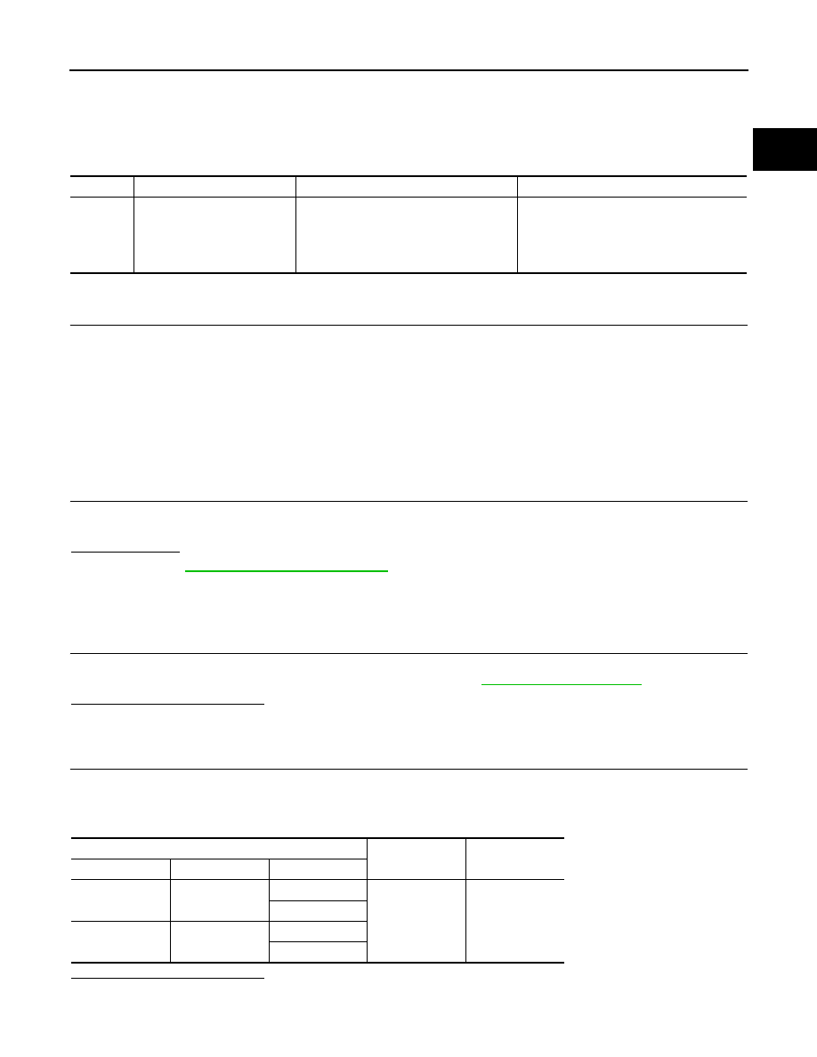
VVEL control shaft position sensor
Ground
Voltage
Bank
Connector
Terminal
1
F72
3
Ground
Approx. 5V
6
2
F70
3
6
EC-1068
< DTC/CIRCUIT DIAGNOSIS >
[VK50VE]
P1608 VVEL SENSOR POWER SUPPLY
3.
CHECK VVEL CONTROL SHAFT POSITION SENSOR POWER SUPPLY CIRCUIT-II
1.
Turn ignition switch OFF.
2.
Disconnect VVEL control module harness connector.
3.
Check the continuity between VVEL control shaft position sensor harness connector and VVEL control
module harness connector.
4.
Also check harness for short to ground and power.
Is the inspection result normal?
YES
>> GO TO 5.
NO
>> GO TO 4.
4.
DETECT MALFUNCTIONING PART
Check the following.
• Harness connectors F10, E10
• Harness for open or short between VVEL control shaft position sensor and VVEL control module
>> Repair open circuit, short to ground or short to power in harness or connectors.
5.
CHECK INTERMITTENT INCIDENT
GI-36, "Intermittent Incident"
Is the inspection result normal?
YES
>> GO TO 6.
NO
>> Repair or replace.
6.
REPLACE VVEL CONTROL MODULE
1.
Replace VVEL control module.
2.
Perform
EC-579, "ADDITIONAL SERVICE WHEN REPLACING CONTROL UNIT (VVEL CONTROL
MODULE) : Special Repair Requirement"
.
>> INSPECTION END
7.
CHECK INTERMITTENT INCIDENT
GI-36, "Intermittent Incident"
Is the inspection result normal?
YES
>> GO TO 8.
NO
>> Repair or replace.
8.
REPLACE VVEL ACTUATOR SUB ASSEMBLY
1.
Replace VVEL actuator sub assembly.
2.
EC-1068, "Special Repair Requirement"
.
>> NSPECTION END
Special Repair Requirement
INFOID:0000000005237566
1.
PERFORM VVEL CONTROL SHAFT POSITION SENSOR ADJUSTMENT
Refer to
EC-583, "VVEL CONTROL SHAFT POSITION SENSOR ADJUSTMENT : Special Repair Require-
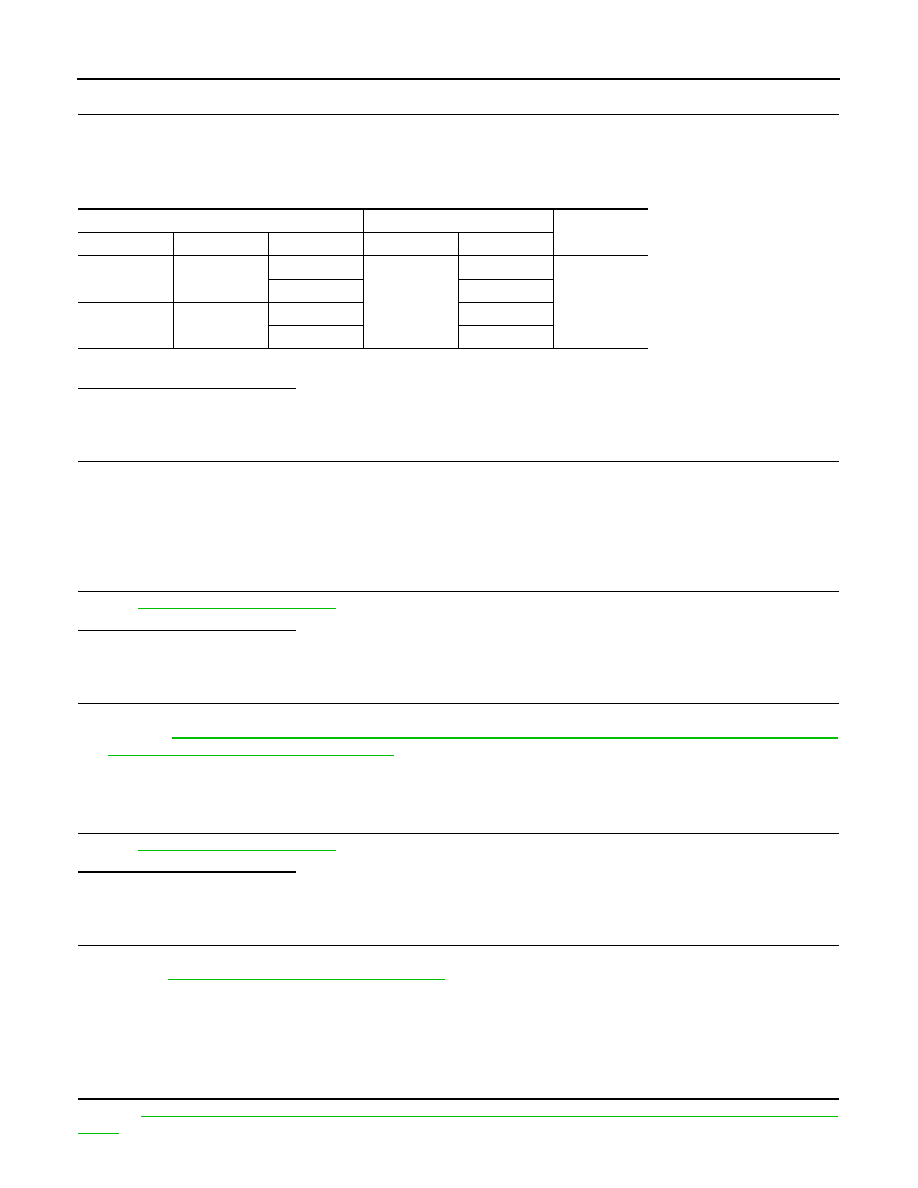
VVEL control shaft position sensor
VVEL control module
Continuity
Bank
Connector
Terminal
Connector
Terminal
1
F72
3
E15
7
Existed
6
20
2
F70
3
9
6
22
Нет комментариевНе стесняйтесь поделиться с нами вашим ценным мнением.
Текст